75
Index
HANDBOOK / KIT DPS
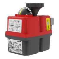
Remove the screw, which is xing the
hand wheel.
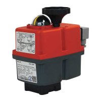
Remove the 6 screws, which are xing
the body to the cover of the actuator.
Carefully lift the cover.
A
B
C
1
4
65
2 3
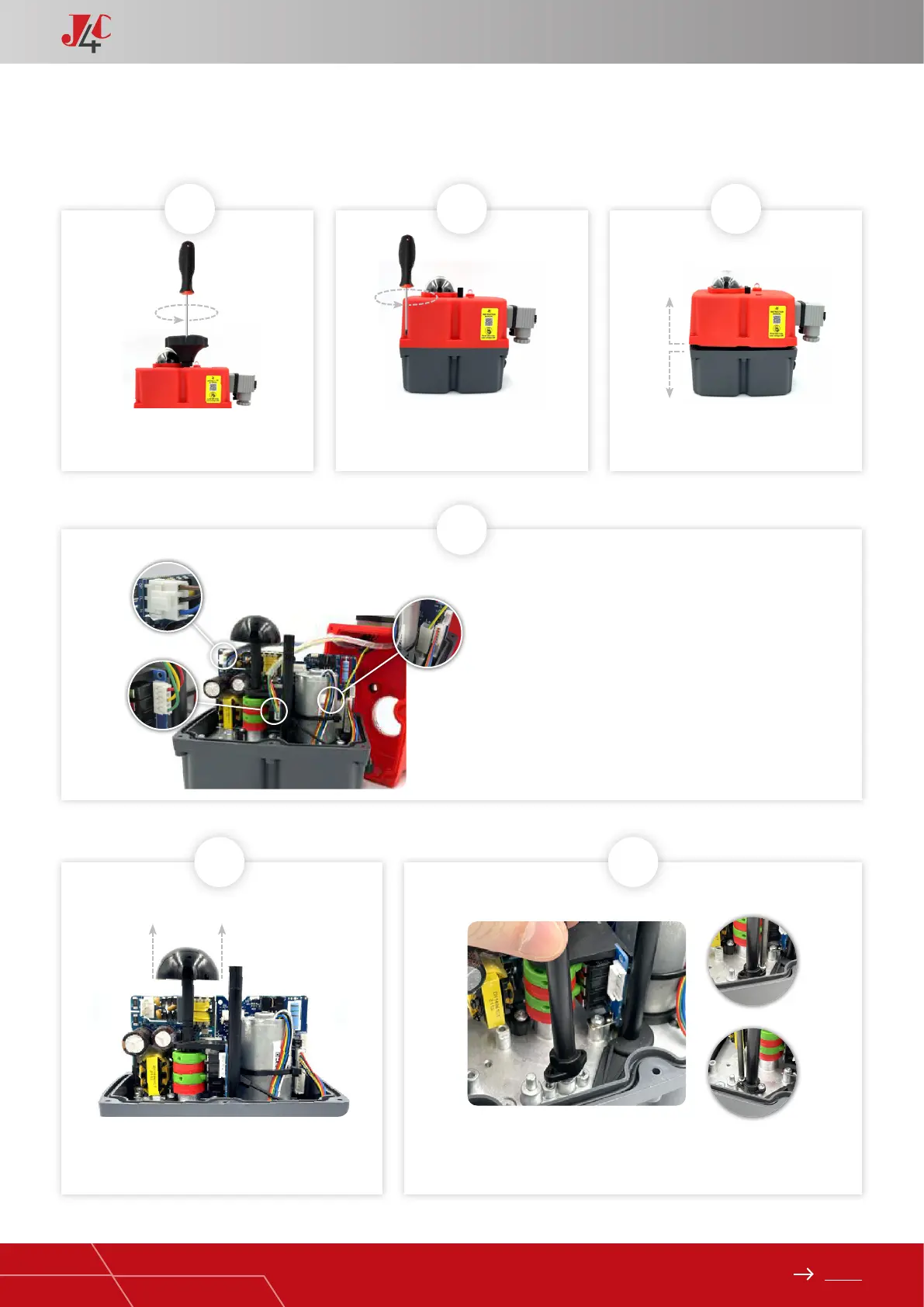
Remove the cables (from the cover) connected to
the actuator PCB (Fig. A, B and C).
Fix the plastic column (Element B) on the base plate, by using 2 sheet metal
xing screws (Element D) (Fig. A, B and C).
Carefully remove the position indicator.
KIT DPS 20/85 ASSEMBLY INSTRUCTIONS — PAGE 1/3
A
B
C