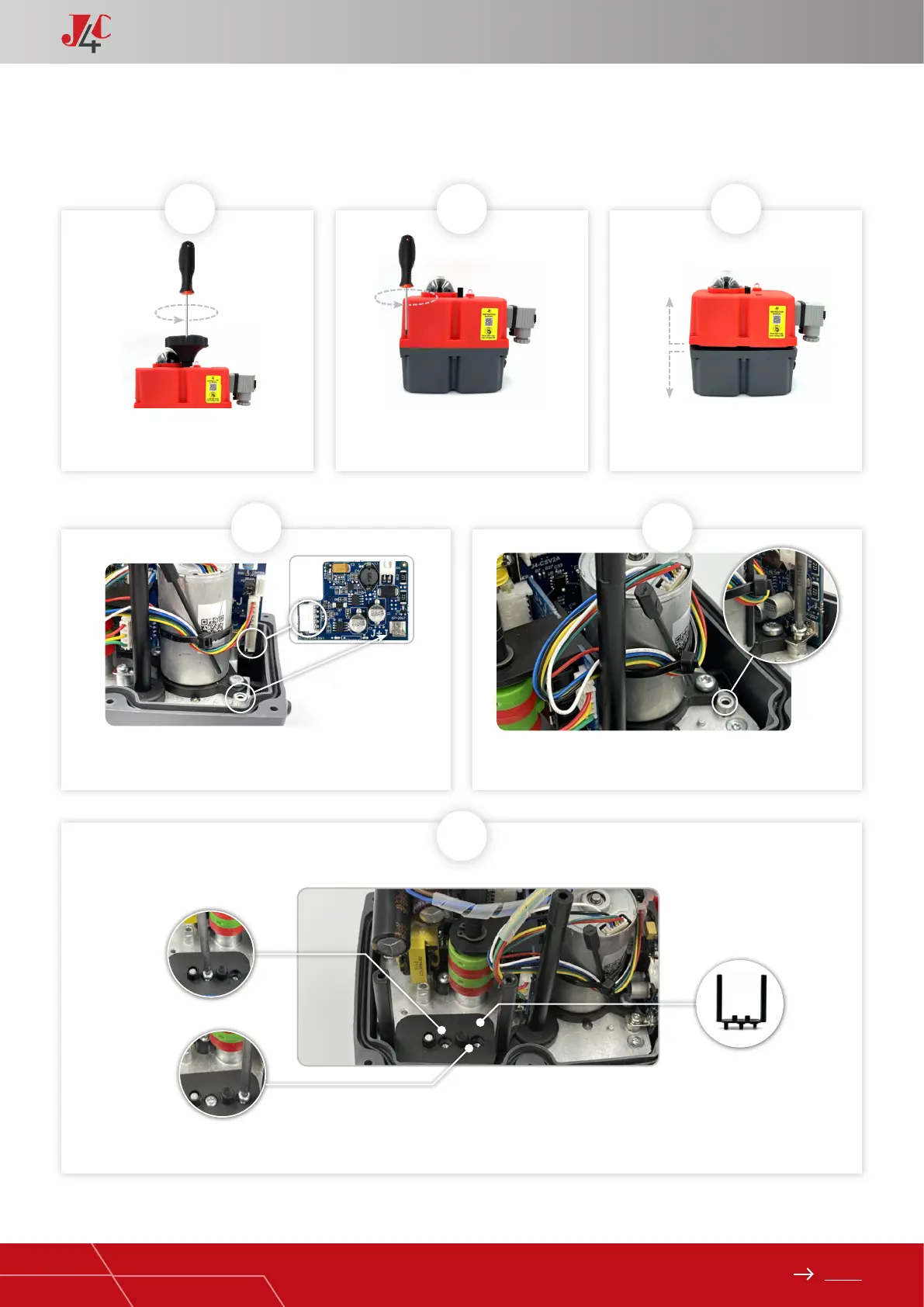
EasyManuals Logo

J+J J4C Series User Manual

J+J J4C Series
109 pages
To Next Page IconTo Next Page
To Previous Page IconTo Previous Page
Page #85 background imageLoading...
Page #85 background image
85
Index
HANDBOOK / KIT BSR
Remove the screw, which is xing the
hand wheel.
Take the BSR PCB (Element A) from the KIT and connect it to the
actuator PCB, by using the connector shown in the picture.
Put the lower battery support (Element B). See (Fig.6A). Fix it by using 2 Sheet metal xing screws (Element E) (Fig.6B & 6C).
Fix it to the actuator metal plate, by using the Sheet metal xing
screw (Element E).
Remove the 6 screws, which are xing
the body to the cover of the actuator.
Carefully lift the cover.
1
4
6
2 3
KIT BSR 20/85 ASSEMBLY INSTRUCTIONS PAGE 1/2
5
C
B
A

Other manuals for J+J J4C Series

Questions and Answers:

Question and Answer IconNeed help?

Do you have a question about the J+J J4C Series and is the answer not in the manual?

J+J J4C Series Specifications

General IconGeneral
BrandJ+J
ModelJ4C Series
CategoryController
LanguageEnglish

Related product manuals