89
Index
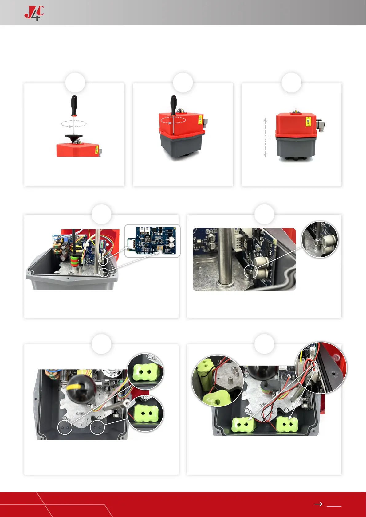
HANDBOOK / KIT BSR
Remove the screw, which is xing the
hand wheel.
Take the BSR PCB (Element B) from the KIT and connect it to the
actuator PCB, by using the connector shown in the picture.
Place the 2 battery packs (Element C) as per picture (Fig. A & B). Place the battery cables so as they remain over the battery pack
(g. 7A). Connect the C1 battery cable to connect 1. Connect the
C2 battery cable to connect 2.
Fix it to the actuator metal plate, by using the Sheet metal xing
screw (Element D).
Remove the 8 screws, which are xing
the body to the cover of the actuator.
Carefully lift the cover.
1
4
6 7
5
2 3
KIT BSR 140/300 ASSEMBLY INSTRUCTIONS — PAGE 1/2
A
B
A
Connect 2
C1 C2
Connect 1