Do you have a question about the JR ProPo Sylphide E12 and is the answer not in the manual?
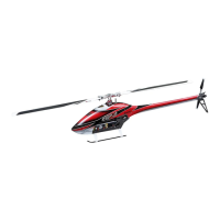
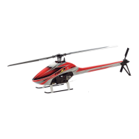
Overview of the Sylphide E12 helicopter and essential safety guidelines.
Advice on seeking expert guidance, handling batteries, and purchasing insurance.
Details regarding the product warranty, including coverage and exclusions.
Information on product liability, risks, and recommended insurance policies.
Procedures for obtaining repair services and contacting distributors.
Guidelines for transferring ownership and proper disposal of electronic waste.
Recommended specialized tools for advanced assembly tasks.
Methods to prevent bolts from loosening due to vibration, using adhesives.
Instructions for using epoxy adhesive for bonding parts.
Guidance on applying instant adhesive for secure part connections.
Symbols indicating parts that require temporary assembly.
Proper use of components for protecting lead harnesses.
Details on identifying and orienting universal links during assembly.
Step-by-step guide for assembling the tail pinion bearing block.
Instructions for installing the motor and its mounting block.
Assembly steps for the swash control lever and its components.
Detailed instructions for assembling the control lever mechanism.
Assembly process for the carbon frame support plate.
Steps for assembling the carbon main tray structure.
First part of the upper frame assembly, including bearing installation.
Second stage of upper frame assembly, connecting cross members.
Final steps for upper frame assembly, including shaft insertion.
Initial assembly steps for the lower frame components.
Second part of lower frame assembly, focusing on tray mounts.
Connecting various frame members and cross members.
Installing the front tray for center of gravity adjustment.
Mounting the landing gear struts and skids.
Assembly of the main helical gear unit.
Assembly of the helical tail gear set.
Installing the carbon tail boom and drive belt.
Mounting the motor onto the helicopter frame.
Final installation and backlash adjustment of helical gears.
Detailed steps for assembling the swash plate mechanism.
Assembly process for the washout unit.
Installing the assembled swash plate and washout onto the main shaft.
Mounting the center hub assembly and head button.
Installing the spindle shaft and its associated components.
Assembling the main blade holder and its linkage arms.
Attaching the main blade holders to the rotor head.
Installing the seesaw mechanism for pitch control.
Mounting the flybar arms and associated links.
Attaching the carbon control paddles to the flybar.
Connecting universal links and fixing the washout stopper for phase adjustment.
Assembling the tail pulley unit.
Initial steps for assembling the ASG tail gear case.
Further assembly of the ASG tail gear case, including shaft movement check.
Final assembly of the ASG tail gear case and shaft alignment.
Assembling the tail slide ring and stopper components.
Installing the tail pitch control levers and associated parts.
Assembling the tail center hub with bearings and washers.
Assembling the tail rotor grips and blade holders.
Attaching the vertical fin to the tail boom.
Assembling the tail boom braces for structural support.
Installing the horizontal fin and connecting tail boom braces.
Mounting the swash servos and rudder servo.
Attaching servo horns to the servo output shafts.
Connecting servos to the swashplate and control surfaces via linkages.
Initial installation of the tail control rod.
Preparing and installing the main tail control rod.
Finalizing the tail control rod connections.
Attaching the FRP canopy and body components.
Mounting the main rotor blades and checking balance.
Configuring the transmitter and receiver for optimal helicopter control.
Adjusting servo neutral positions and ensuring swashplate is level.
Verifying and adjusting swashplate movement at high and low pitch.
Setting up the rudder servo direction, travel, and gyro sensitivity.
Adjusting rotor pitch, control movements, and pitch/throttle curves.
Guidelines for rotor speed, backlash, flight time, and connector usage.
A comprehensive checklist before the initial flight.
Adjusting main rotor blade pitch for uniform trajectory and reduced vibration.
Final checks on bolts and rotating parts after assembly.
Safety measures and checks to perform before powering up or flying.
Safety guidelines to follow while the helicopter is in the air.
Checks and maintenance steps after completing a flight.
Instructions for applying decals to the helicopter body.
| Brand | JR ProPo |
|---|---|
| Model | Sylphide E12 |
| Radio | Not included |
| Servos | Not included |
| Gyro | Not included |