5-4
JMA-9100/7100 Installation Manual > 5.OPTION UNIT > 5.1 INSTALLATION OF INTERSWITCH UNIT
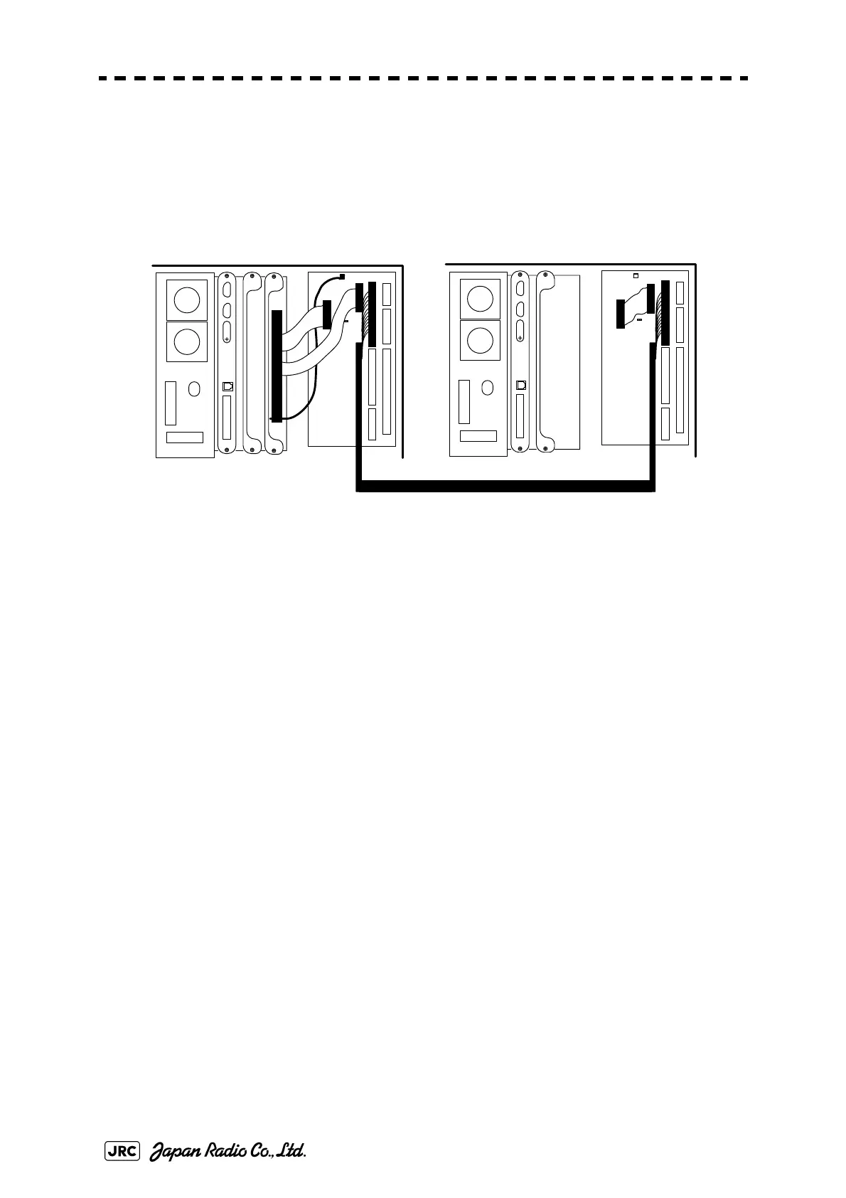
6)
Connect the cable (2695111153) between terminal board circuit TB4201
located on the port-side radar display unit and on the starboard-side radar
display unit.
Fig 5-5: Installation of NQE-3141-2
7)
Confirm the installation. See Section 5.1.5Confirmation after installation.
b. NQE-3141-4A
1)
Securely ground the included earth plate to the hull's earth.
2)
Connect the cable (2695111153) between interswitch unit NQE-3141-4A
and terminal board TB4201 located on the each radar display unit. See Fig
5-13: NQE-3141-4A Inter-board connection diagram.
3)
Confirm the installation. See Section 5.1.5Confirmation after installation.
TB 2
TB4101(ANT)
TB4301
(P WR SRC)
TB4401 (EXT RADAR)
TB4201 (ISW IN/OUT)TB4501 (OPTION)
TB4801 (LOG)
J4308
ISW
J4307
J4306
TB2
TB4101(ANT)
TB 430 1
(P WR S RC)
TB4401 (EXT RADAR)
TB4201 (ISW IN/OUT)TB4501 (OPTION)
TB4801 (LOG)
J4308
ISW
Starboard Side
No.2 RADAR
Port Side
No.1 RADAR
Interswitch Unit (NQE-3141-2)
Flat
Cable
Flat
Cable
RED-WHT
2695111153
CH1
CH2
J4307
J4306
Flat
Cable
 Loading...


