5-10
JMA-9100/7100 Installation Manual > 5.OPTION UNIT > 5.1 INSTALLATION OF INTERSWITCH UNIT
• Although dip switch settings are basically the same as the settings shown in Fig
5-11: Access to Lower Board of NQE-3141-8A, it is necessary to make settings
for each of the two SW12.
• It is necessary to remove six screws marked in the above drawing in order to
access the first story portion.
• With regard to SW12 board located at the upper position, make settings for
CH1 to CH4.
• With regard to SW12 board located at the lower position, make settings for
CH5 to CH8.
• CH1 to CH4 displayed on the terminal block mean CH5 to CH8.
• Settings have been made for SW11 and SW13 upon shipment. Do not change
those settings.
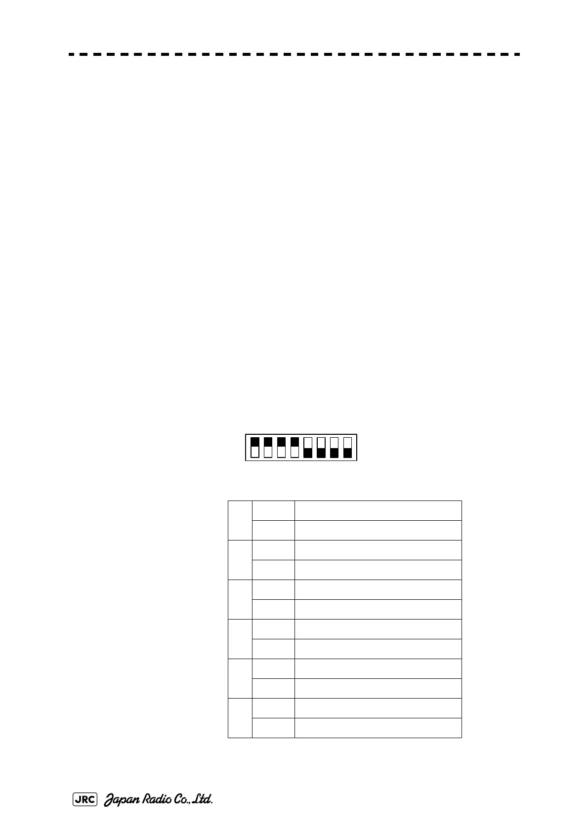
• Setting of upper CCL-304R, SW12 (radar connection setting)
Radar Connection Setting
Factory default setting (bit1-bit2-bit3-bit4)
SW11-upper OFF-OFF-OFF-ON
SW11-lower OFF-OFF-ON-ON
SW13-both OFF-OFF-OFF-OFF
1ON
No. 1 display unit connected
OFF
No. 1 display unit NOT connected
2ON
No. 1 antenna connected
OFF
No. 1 antenna NOT connected
3ON
No. 2 display unit connected
OFF
No. 2 display unit NOT connected
4ON
No. 2 antenna connected
OFF
No. 2 antenna NOT connected
5ON
No. 3 display unit connected
OFF
No. 3 display unit NOT connected
6ON
No. 3 antenna connected
OFF
No. 3 antenna NOT connected
1 234
ON
OFF
5768
 Loading...


