16
H:\0 - Quality Documents\2 Department\Tech Serv\Application tooling\Presses\AP-K2N\TS010-00 AP-K2N Operation
Manual.doc
6.2 Bell Mouth Adjustment
When using the MK-L Applicator
Adjust the terminal feed position with reference to the
bell-mouth position. Refer to section 6.1
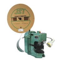
When using the MKS-L Applicator (old type)
Move the entire feed-plate to obtain the desired bell-
mouth crimp. First, loosen the feed-finger retaining screw
in the feed-finger holder. Next, loosen the two cap head
socket screws in the slots on the base of the applicator
(see photograph).
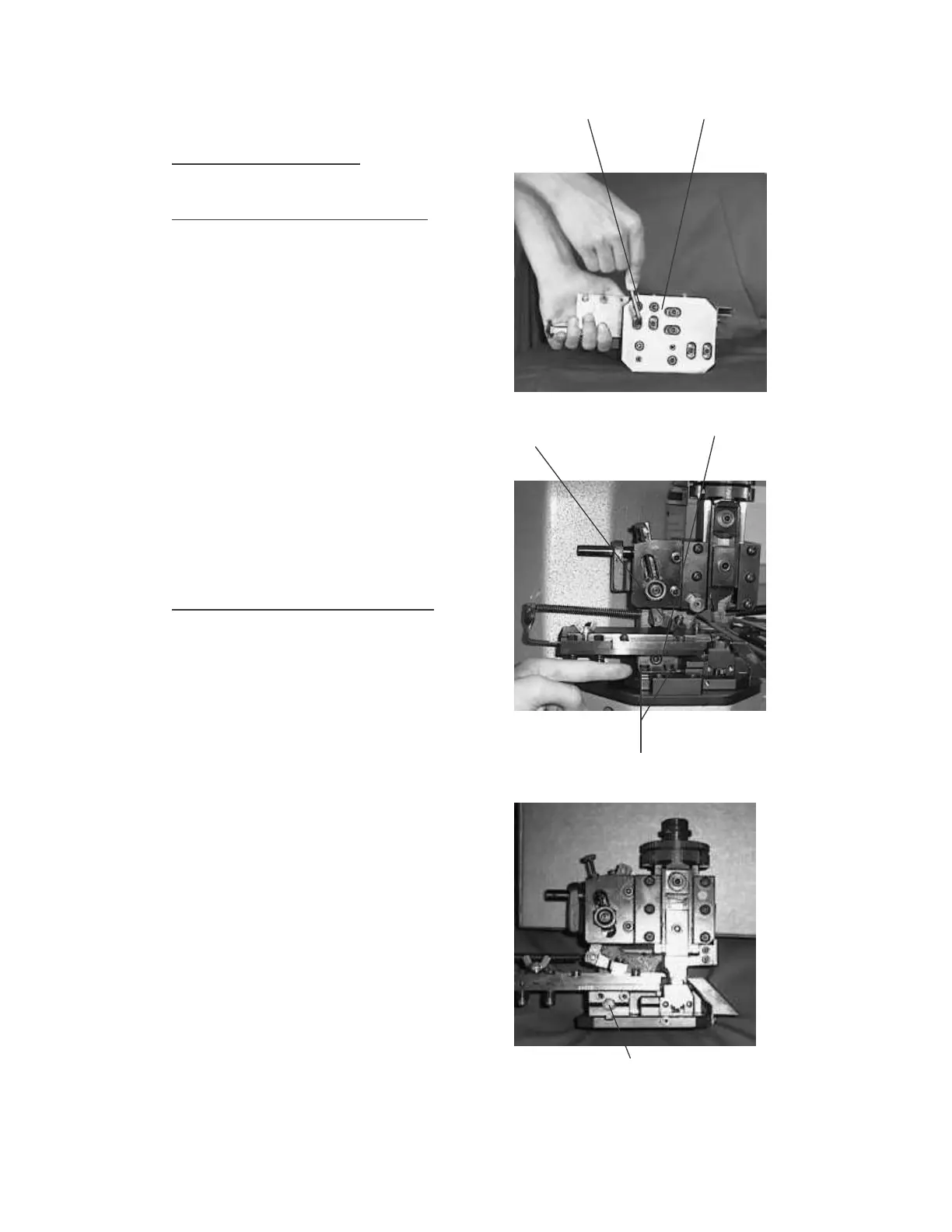
With the aid of a flat ended screwdriver, rotate the
adjusting screw in the front of the adjustment carriage,
turn the screw clockwise to increase the bell-mouth
(move the guide rails towards the front of the press), and
counter-clockwise to decrease the bell-mouth (move the
guide rails towards the back of the press).
Re-tighten the adjustment screws on the base of the
applicator, centralize the feed-finger in the slot in the
guide rail and tighten the screw.
Check the bell-mouth on the resultant crimp and re-
adjust if necessary.
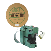
When using the MKS-L Applicator (new type)
Move the entire feed-plate to obtain the desired bell-
mouth crimp. First, loosen the feed-finger retaining
screw in the feed-finger holder. Next, loosen the two
hexagon-headed bolts situated on the front of the
adjustment carriage just above the top surface of the
applicator base-plate.
With the aid of a 5mm hexagon key, rotate the screw in
the front of the adjustment carriage, turn the screw clock-
wise to decrease the bell-mouth (move the guide rails
towards the back of the press), and counter-clockwise to
increase the bell-mouth (move the guide rails towards
the front of the press).
Re-tighten the adjustment bolts, centralize the feed-
finger in the slot in the guide rail and tighten the screw.
Check the resultant crimp and re-adjust if necessary.
There is a crimping manual available from the JST
Technical Department detailing the points to inspect on a
crimped terminal to achieve results as per our
specifications.
A copy is issued with every AP-K2N Crimping machine
supplied to a customer but please contact JST if you
require further copies.
Slot-head adjustment screws
Feed-finger screw Adjustment screw
Hexagon nuts
Adjustment screw