2
© 2017 JT Communications LLC, Ocala, Florida, USA
All radiohts reserved.
PRODUCT DESCRIPTION:
TuneMatic is a self-contained antenna controller which will automatically adjust the resonant frequency of a
screwdriver/motorized antenna. TuneMatic operates over a frequency range between 1 and 60 MHz, and
supports a wide variety of screwdriver-type tunable antennas. TuneMatic utilizes frequency, antenna current,
VSWR, and pulse position measurements of the antenna to perform the proper tuning, and keeps track of the
parameters of the antenna by storing the tuning data in a series of internal reserved memory banks, based on
frequency. TuneMatic is independent of radio make and model and will support any HF radio with a PTT
control line and switched power
A- INSTALLATION CONNECTIONS:
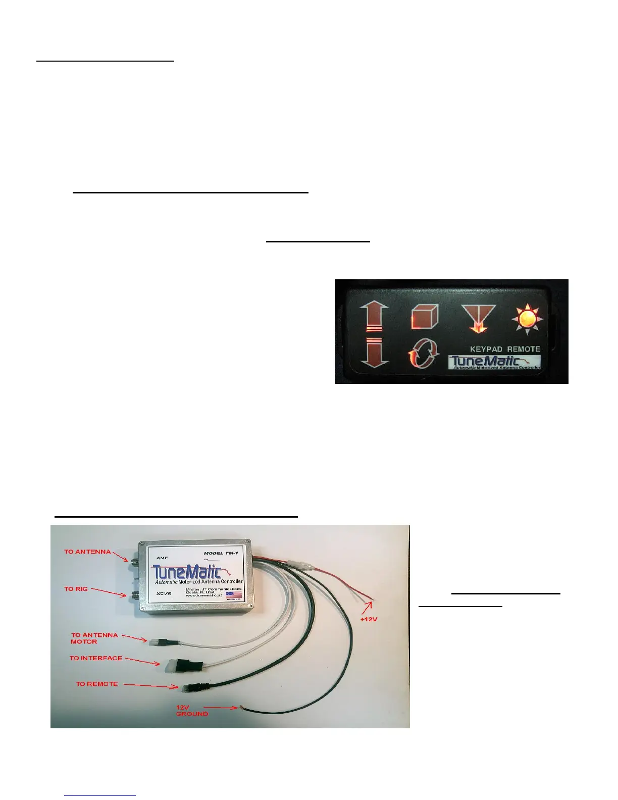
REMOTE HEAD
The remote head allows you to control the functions of TuneMatic from a remote location. The buttons are
identified as follows:
UP ARROW- Allows antenna to move up in direction.
DOWN ARROW- Allows antenna to move down in
direction.
UP/DOWN (both) – resets current limit when not
initialized, and “parks” antenna (moves to lowest position)
after TuneMatic has been initialized.
BOX (STORE)- Stores memories after a good VSWR
tune. See Section 5 for further instructions.
CIRCULAR ARROWS (INIT) - Performs system initialization. See section 3 for further instructions. This button
also doubles as a tune cancel feature. See section 6 on the cancel feature.
STORE/INIT (both)- During power up, pressing and holding both buttons performs factory reset. See section 7
for further instructions.
ANTENNA WITH DOWN ARROW (TUNE)- Performs autotune mode. See section 6 for further instructions
SUN SYMBOL- This LED flashes during antenna movement. See section 1, FIRST TIME OPERATION section
for further instructions. When power is applied, the buttons will illuminate.
MAIN UNIT CONNECTIONS/CABLES
1) 12v power leads: These
leads can be paralleled with
radio power if desired, as they
draw no current until TuneMatic
is powered up by Radio Control
cable. NEGATIVE GROUND
SYSTEM ONLY!
RED (with fuse): +12-15VDC-
connect to +12v power capable
of 3 amps of current.
BLACK- Ground- connect to
negative ground source.