3
© 2017 JT Communications LLC, Ocala, Florida, USA
All radiohts reserved.
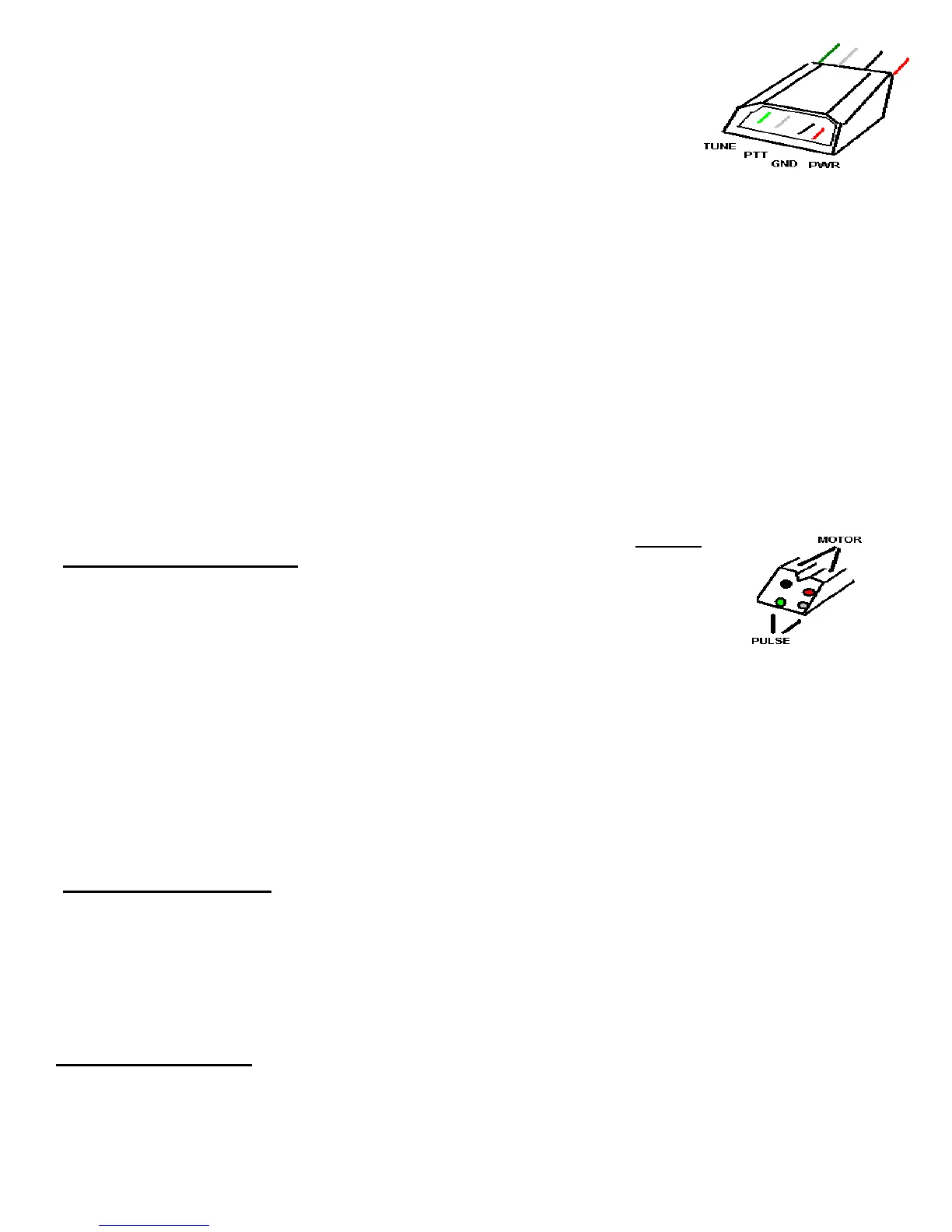
2) Interface: There are four (4) leads on this 4 pin male connector. It connects
through the radio interface box for the specific radio you are using. The color code
is as follows:
GND (BLACK [pin 2]) connects to radio ground or common.
PWR(RED[pin 1])- When this line goes between 8-14v, it turns on TuneMatic.
Typically it is connected to the switched 12V DC from radio. When power is applied from radio TuneMatic
turns on, as well as Remote Head backlights. The current requirement for this connection is less than 0.1 A
at 12-14 DC.
PTT (WHITE or YELLOW [pin 3])- This line goes low (within 0.7v of ground) when TuneMatic requires
radio to be keyed. This lead will sink up to 0.5A of current, thermally limited.
TUNE (BLUE or GREEN [pin 4])- When this is low, it places TuneMatic in a TUNE mode. Not used.
3) Coax connections- The two SO-239(UHF) connections are identified as follows:
RIG - Connect this to the radio through the supplied 3’ PL-259 jumper.
ANT - Connect this to either the antenna, or input of amplifier if using the amp option- then connect
amplifier output to antenna lead.
4) Remote / RJ-45 couplers(2)- These cables/connections mate with the remote head. Although the factory
jumper supplied is 12’ in length, other lengths can be used, however lengths over 50 feet should be avoided.
The female couplers on each end allow conventional RJ-45 CAT-5 cabling straight-thru
connections between connections. All 8 leads need to be wired end to end. DO NOT
USE A CROSSOVER CABLE.
5) Motor/pulse control- Contains the bi-directional motor leads (floating from ground)
and pulse counter connections to the antenna motor. Be sure to follow the antenna
manufacturers directions with regard to RF isolating this line at the antenna. If
using other than TarHeel antenna, a factory-supplied pigtail can be used to wire to your specific
antenna. RED/BLACK are the motor leads, and the other remaining leads (not polarity sensitive) are
the motor pulse leads. Observe connection to motor leads so that antenna moves to LOWER
frequency when pressing UP on remote.
ADDITIONAL OPTIONS (if installed):
1) Amplifier keyline(paired and labeled)- This line connects in SERIES with the Radio and external
amplifier keyline. There is no polarity on this normally closed connection. It opens when TuneMatic begins
TUNE mode, then closes after tune is completed. See amplifier supplement sheet, supplied with units
containing this option.
RADIO INTERFACE:
The radio interface is the communications between the the TuneMatic and your specific radio (refer to the
interface supplement) for wiring information and specifics). The factory-supplied radio interface controls the
keying and control for the specified radio, using a keyline and switched 12v. Each manufacturer is unique in
the communications, and the interface allows TuneMatic to work universally.
B) INSTALLATION:
 Loading...