Home
JUKI
Sewing Machine
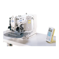
LK-1930
JUKI LK-1930 Engineer's Manual
187 pages
Manual
Specs
Ask a question
To Next Page
To Next Page
Loading...
29326600
No.E329-03
R
ENGINEER’S MANUAL
Computer-controlled High Speed
Bar Tacking Industrial Sewing Machine
LK-1910 / LK-1920
Computer-controlled High Speed Bar Tacking
Industrial Sewing Machine with Input Function
LK-1930
2
Table of Contents
Default Chapter
3
Table of Contents
3
Specifications
6
Configuration
7
Names of Main Unit
7
Name of the Switches on the Operation Box (LK-1910, 1920)
8
Names of the Switches for the Sewing Machine Operation (LK-1930)
9
Names of Display Indications (LK-1930)
9
Adjustments
10
Adjustment of the Main Shaft Components
10
Adjusting the Play of the Main Shaft
10
Installing the Main Motor
10
Adjusting the Main Shaft Sensor
12
Adjusting the Intermediate Presser Components (LK-1920, 1930)
12
Adjusting the Position of the Intermediate Presser Cam
12
Installing the Intermediate Presser Bar Guide Bracket Support Plate
14
Adjusting the Position of the Intermediate Presser Bar Guide Bracket
14
Height of the Intermediate Presser Adjusting Screw
16
Adjusting the Position of the Intermediate Presser Solenoid
18
Adjusting the Wiper Components
18
Adjusting the Position of the Wiper
18
Adjustment of the Shuttle Driver Shaft Components
20
Adjusting the Longitudinal Position of the Oscillator
20
Adjusting the Backlash of the Oscillator Gear
20
Removing the Play of the Shuttle Driving Shaft
20
Adjustment of the Thread Trimmer Mechanism Components
22
Adjusting the Thread Trimmer Cam
22
Adjusting the Thread Trimmer Link Stopper Screw
22
Position of the Thread Trimmer Shaft
24
Position of the Cam Installing Link Stopper
24
Position of the Thread Trimmer Magnet Arm
26
Position of the Moving and Counter Knives
28
Height of the Moving and Counter Knives
28
Inclination of the Blade Point of the Counter Knife
28
Adjustment of the Tension Release Components
30
Installing Position of the Tension Release Notch
30
Position of the Tension Release Stopper
30
Floating Amount of the Thread Tension Disk
30
Adjusting the Sensor Components
32
Mechanical Origin
32
Adjusting the y Origin Sensor
32
Adjusting the X Origin Sensor
34
Adjustment of the Feed Mechanism Components
36
Adjusting the Position of the X Motor Base
36
Adjusting the Positions of the X Motor and the y Motor (Adjusting the Backlash of the Driving Gear)
36
Installing the Feed Plate Support Plate
38
Installing the Feed Plate
38
Installing the Feed Bracket
40
Adjusting the Bobbin Thread Winder Components
42
Adjusting the Position of the Bobbing Winder Driving Wheel
42
Adjusting the Presser Components
42
Joining of the Presser Plate and the Presser Shaft (Solenoid Type)
42
Adjusting the Position of the Presser Shaft Guide (Solenoid Type)
44
Adjusting the Presser Cylinder (Pneumatic Type Only)
44
Height of the Slider (Pneumatic Type Only)
46
Adjusting the Speed Controller
46
Adjustment of the Sewing Components
48
Adjusting the Position of the Shuttle Upper Spring
48
Shuttle Felt
50
Shape of the Shuttle Race Ring
50
List of Replacement Components for Standard and Heavy-Weight Materials
52
Stitching Pattern
53
Service Pattern
53
Patterns for Users
53
Memory Switch
55
Operating Method (LK-1910, 1920)
57
How to Start the Memory Switches
57
How to Finish the Memory Switches
60
How to Use the Memory Switch (Lk-1930)
61
Memory Switch
61
Explanation of the Operation Panel to be Used
61
How to Start the Memory Switches
62
How to Change the Contents of each Setting
62
Write-In of the Contents of Setting
63
Writing/Reading of the Contents of the Memory Switches Onto the Floppy Disk
64
Description of the Memory Switches (Lk-1930)
65
Initialization of the Memory Switch (Lk-1930)
90
How to Initialize
90
Table of the Initial Setting
91
Complementary Explanation of Function Nos. (Lk-1930)
95
Fixed Retracted Position Setting (Function No. 003)
95
How to Use the Bank Function (Function No. 021 and 075)
96
Combination Function
101
How to Set the Sequence of the Feeding Frame Operation (Function Nos. 030 to 033, 98, 99)
104
Test Mode (Lk-1910, 1920)
109
Operating Method
110
How to Start the Test Mode
110
How to Check each Test Program no
112
How to Finish Test Mode
118
Test Mode (Lk-1930)
119
How to Start the Test Mode
119
Test Mode Function
119
Parts Grease or Lock-Tight Paint Is Applied
124
Presser Dimensions
126
How to Use Optionals
128
Needle Cooler (Pneumatic Type Only)
128
Installing Procedure of the Needle Cooler
128
How to Use the Needle Cooler
130
Inverting Clamp Device (FU-02S, FU-02L)
132
Installing the Inverting Clamp Device
132
How to Use the Inverting Clamp Device
134
Tension Controller No. 3 (Pneumatic Type)
136
Installing the Tension Controller No. 3 (B50192220B0)
136
How to Use the Tension Controller No. 3
140
Disk Floating Device for Basting Stitch
142
Installing Disk Floating Device
142
How to Use Disk Floating Device
142
Table of Error Indication ( Lk-1910, 1920)
144
Error Message Table (Lk-1930)
145
Power Switch Connection Diagram
147
For 3-Phase 200, 220 and 240V
147
For Single-Phase 100V, 110V, 120V, 200V, 220V and 240V
147
For 3-Phase 220V, 240V, 380V, 400V and 415V
148
For Single-Phase 220V, 240V, 380V, 400V and 415V
149
Connection of the Power Plug
150
Overseas Market : 100V Series 200V Series
150
Overseas Market : 380V Series
151
Change of the Power Voltage
152
Change of the Voltage from 100 to 240 V
152
Change of the Voltage from 220 to 415 V
152
Maintenance and Inspection
153
Replacing the Printed Circuit Boards
153
MAIN Circuit Board
153
SERVO Circuit Board
153
PMDC Circuit Board
153
POWER Circuit Board
154
Troubles and Corrective Measures
155
Mechanical Parts
155
With Regard to Sewing
157
Electrical Parts (Also, Refer to Block Diagram.)
164
Curcuit Diagram
171
Block Diagram (LK-1910, 1920)
171
Block Diagram (LK-1930)
172
Power Circuit Diagram a (LK-1910, 1920)
173
Power Circuit Diagram a (LK-1930)
174
Power Circuit Diagram B (LK-1910, 1920)
175
Power Circuit Diagram B (LK-1930)
176
Head Sensor Circuit Diagram
177
Solenoid Valve Circuit Diagam
178
Solenoid Circuit Diagram
179
Stepping Motor Circuit Diagram
180
Pedal Switch Circuit Diagram
181
3-Step PK Pedal Circuit Diagram
182
Servo Motor Circuit Diagram
183
Pneumatic System Circuit Diagram
184
Drawing of the Table
185
Other manuals for JUKI LK-1930
Instruction Manual
264 pages
Handbook
272 pages
Need help?
Do you have a question about the JUKI LK-1930 and is the answer not in the manual?
Ask a question
JUKI LK-1930 Specifications
General
Needle Type
DB x 1
Motor
Servo Motor
Weight
45 kg
Lubrication
Automatic
Motor Power
550 W
Type
Lockstitch
Hook
Rotary hook
Thread Type
Polyester
Related product manuals
JUKI LK-1941
126 pages
JUKI LK-1910
67 pages
JUKI LK-1900A
83 pages
JUKI LK-1904F
272 pages
JUKI LK-1901A
152 pages
JUKI LK-1903BN
37 pages
JUKI LK-1903A-305
83 pages
JUKI LK-1900S Series
92 pages
JUKI LK-1900B series
110 pages
JUKI LK-1900A Series
124 pages
JUKI LK-1903B Series
3 pages
JUKI LK-1900BN Series
115 pages