ASSEMBLY INSTRUCTIONS
E
I
FF
x2
x2
AA
x2
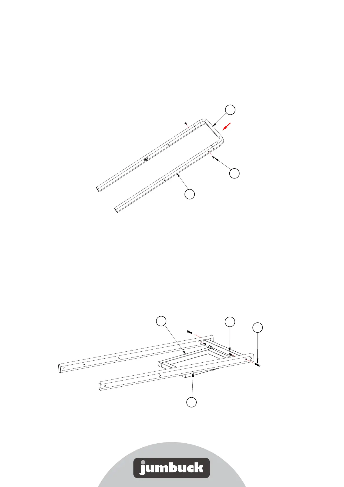
Step 1
Insert the 2 left long leg sections (C) over either side of the upper leg support (J),
ensuring the ring side of the spring pin is facing inwards. Use a phillips head
screwdriver to secure with 2 x M6x12 screws (AA).
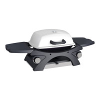
Step 2
Attach the gas cylinder mounting base (E) to the 2 right leg sections (I) by aligning the
mounting holes on part E with the mounting holes on parts I. Use a phillips head
screwdriver to secure with 2 x M6x12 screws (AA) through the metal nutserts on the
inside face of the legs, and 2 x M6x30 screws (FF) through the holes from the outside.
AA
J
C
x2
x2