9
3 RTD temperature probe
3 RTD temperature probe
3.1 Design
An RTD temperature probe essentially comprises a temperature sensor, connection lines, and a protec-
tion tube. The temperature sensor is connected to a connection line/connection wires, insulated, and in-
serted into a protection tube (usually filled with a heat-conducting medium). The connection side can be
designed as a line end that has been kept free, or designed with a terminal head, with a connector, etc.
Alongside a variety of special versions, some RTD temperature probes are described fully by standards,
such as
• Straight thermometers with interchangeable sensor units – DIN 43764
• Threaded-stem thermometers with G 1/2 mounting thread – DIN 43765
• Threaded-stem thermometers with G 1 mounting thread – DIN 43766
• Welded-stem thermometers – DIN 43767
• Thermometers not fitted with protecting tubes – DIN 43769
• Fast response thermometers – DIN 43771
In some cases, individual components are also described by standards, such as
• Protective tubes – DIN 43772
• Flanges – DIN EN 1092
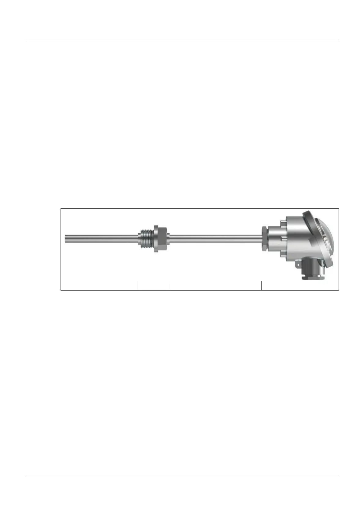
Variant with terminal head
(1) (2) (3) (4)
(1) Protection tube
• In contact with the process
• Protects the measuring insert against the medium (pressure, flow, etc.)
• On versions with immersion sleeves, the need to open the process can be avoided,
for example to replace the thermometer or measuring insert
(2) Process connection
• Interface with the process
• Thread, flange, etc.
(3) Extension tube
• Protects the components (such as the transmitter) against excess temperatures in the area of
the terminal head
• Spans the insulation, such as on pipes or furnaces;
the terminal head should always be outside the insulation
(4) Terminal head
• Contains and protects the connection components
• Display optional

 Loading...