Do you have a question about the Jung RTR231 and is the answer not in the manual?
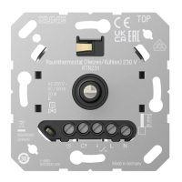
This document describes the JUNG Room Thermostat (heating/cooling) 230 V, Art. no.: RTR231, an electronic room temperature controller designed for managing electrothermal valve drives in closed rooms. It is intended for mounting in appliance boxes conforming to DIN 49073.
The room thermostat offers a range of functionalities for precise temperature control:
ECO Operation: This feature allows the temperature to be set to a lower ECO temperature at specific times, rather than maintaining a constant comfort temperature. By connecting the input terminal to 230 V, the temperature is reduced by 4 °C, and the status LED illuminates green. This function is typically controlled by a central clock. In cooling mode, the wiring of the input terminal is ignored.
Cooling Mode: The device supports cooling functionality, often used with modern heat pump systems. The cooling temperature can be adjusted using the control knob. Switching between heating and cooling modes is achieved either via the control knob or by wiring the input terminal "C" with 230 V.
Temperature Drop Detection: In instances of a rapid temperature drop, such as when a window is opened, the system automatically regulates to a frost protection temperature of 5 °C for a maximum of 30 minutes. This operation can be canceled by pressing or turning the control knob.
Offset Adjustment: This function enables the adjustment of the control knob's position to align with the actual room temperature. This ensures consistent temperature indications across different rooms. An adaptation of up to +/- 3 °C is possible.
Controller Adaptation: The control behavior can be adjusted based on the specific heating system.
Setting the Valve Type: The device can be adapted to the specific electrothermal valve drive used. Options include "deenergised opened" (NO) or "deenergised closed" (NC), with "deenergised closed" being the factory setting.
Frost Protection Function: Prevents the room temperature from falling below 5 °C.
Silent Switching: Ensures quiet operation of the device.
Valve Protection Function: Automatically opens and closes the valve once a week to prevent seizing.
Permanent LED Operation: The status LED can be set to operate continuously with reduced brightness during active heating or cooling phases.
Increasing or Reducing Room Temperature: Turn the control knob right or left. If the setpoint temperature is not reached, the LED illuminates for up to 2 minutes in the color of the current operating mode. This indication can also be set to occur during the entire heating/cooling process. The middle position regulates to approximately 20 °C. The lowest setpoint is 5 °C, and the highest is 30 °C.
Indication of Current Operating Mode: Briefly press the control knob. The LED will illuminate for 10 seconds in the color corresponding to the current operating mode:
Switching Off Temperature Control: Press the control knob for more than 2 seconds until the LED illuminates orange. The device enters frost protection mode (5 °C). Turning the control knob will cause the LED to flash orange for 10 seconds. To reactivate temperature control, press the control knob again for more than two seconds; the device will return to the previous operating mode.
Manual Switching Between Heating and Cooling Mode:
Calibrating Actual and Setpoint Temperature:
Activating/Deactivating Permanent LED Operation: Press the control knob for longer than 10 seconds until the LED illuminates or flashes magenta.
Setting Temperature Limits: The adjustment rings on the central plate allow limiting the temperature setting range (e.g., from 5-30 °C to 10-25 °C). To do this, pull off the control knob to reveal the adjustment rings. Turn the large blue ring clockwise for the minimum temperature and the small red ring anticlockwise for the maximum temperature. Each notch corresponds to approximately 1 °C.
Setting the Offset: This function allows adjusting the control knob's position to match the actual room temperature, ensuring consistent temperature readings across different rooms (up to +/- 3 °C). This is only possible if the lower temperature limit has not been raised by the blue setting ring.
Installation Location:
Commissioning: The unit calibrates itself within the first 90 minutes after switching on mains voltage. Control deviations may occur during this period.
Safety: Electrical devices must only be mounted and connected by electrically skilled persons. Always disconnect power before working on the device or load to prevent electric shock. The manual is an integral part of the product and must remain with the end customer. During renovation, the temperature sensor (6) must not become dirty or painted over.
| Brand | Jung |
|---|---|
| Model | RTR231 |
| Category | Thermostat |
| Language | English |