Do you have a question about the Jungheinrich SLT 100 and is the answer not in the manual?
Details the SLT 100 charger's design, electronic system, charging voltage, current, protection features, and transformers.
Explains charging electronics, LEDs for status, control key operation, and safety cut-outs.
Safety regulations for maintenance personnel, fire protection measures, and handling of lead-acid batteries.
Steps for connecting, starting, and managing charging operations, including fault indications and safety cut-outs.
Identifies causes and elimination measures for pump issues and charging time not reducing.
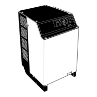
The SLT 100 is a battery charger designed for the fully automatic charging and recharging of lead batteries. It operates according to the Wa characteristic curve specified in DIN 41774, which is optimized by current pulses at the end of the charge. This current characteristic curve slopes downwards as the battery charge level rises, allowing for optimal charging. The charger's safe functioning is ensured by reliable charging electronics that monitor the battery charging operation.
The SLT 100 battery charger is intended for stationary use only and must always be operated with its housing closed. It is forbidden to loosen or remove any parts of the housing or any suppressor elements. No objects should be placed on the charger, nor should anyone climb onto it. Additional components may only be installed after written approval from the manufacturer. The user is responsible for selecting the assembly location, ensuring it does not affect devices sensitive to electromagnetic interference. The charger should be stored in enclosed areas, and its operation is permitted only in specially provided spaces.
The charger is self-cooled and designed for a maximum ambient temperature of 40 °C and a maximum relative humidity of 80%. Minimum ambient temperatures are -20 °C for storage and 0 °C for operation. If the charger thaws due to sudden temperature changes, it should be left for at least 3 hours before being switched on again.
The SLT 100 charging electronics monitor and control the charging operation. The progress of the charging operation is indicated by light-emitting diodes (LEDs) on the front panel. An electronic monitoring unit detects the gassing time and determines the optimum recharging time based on the charged capacity (Ah balancing). Charging starts automatically with a time delay of approximately 10 seconds to protect the plug contacts after the battery has been connected. The control key can be used to cancel operation at any time. The standby, charging, charging completed, and compensation charge conditions are indicated by specific LEDs.
An automatic safety cut-out is provided if the gassing voltage is not reached within an initial charging phase of 12 hours. This is indicated by a yellow warning LED flashing three times. If the transformer overheats, a warning is indicated by the same LED flashing four times. Once the transformer temperature returns to the permissible range, charging resumes, and the LED turns off. The charging electronics are zero-voltage proof, meaning no malfunctions occur due to mains failures, as all times are stored, and charging recommences from the point of failure.
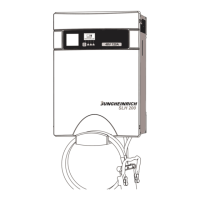
The SLT 100 charger is supplied with a charging cable. The charging cable connections with strain relief are accessible by opening the yellow panel. Only charging cables provided by the manufacturer should be used. For mains connection, all operations involving opening the charger must be performed solely by trained and authorized electricians. The battery and mains plugs must be removed before opening the charger. The mains voltage must correspond with the voltage indicated on the identification label, which is located on the rear wall of the unit. Fuse protection of the mains cable to the battery charger is the customer's responsibility, and the fuse must have a delay-action release characteristic.
The charger can be equipped with an optional Aquamatic system, which controls an external solenoid valve of an automatic water refilling system. When a cell voltage of 2.4 V/cell is reached, a relay contact triggers a pulse train (6-7 pulses of 3 seconds duration, followed by a maintained contact for 7 minutes). The contact is potential-free, and a 230 V power connection of the battery charger is available.
Another option is an electrolyte circulation pump. The charger has an option for controlling this pump. The Aquamatic and electrolyte circulation systems are monitored, and any faults are displayed on the front panel. The connection of external additional equipment must only be carried out by skilled electricians.
If the battery remains attached to the charger after the charging time has ended, an 8-minute trickle charge will follow every 8 hours, and after 24 hours, a one-off compensation charge lasting 2 hours will occur. A controlled thorough acid mixing by means of current pulses is carried out at the end of the recharging phase.
When connecting the charger, ensure the charging cable contact is secure to prevent constant charging current fluctuations that could affect the charging electronics and show an incorrect display. Charging will not start if the battery voltage is outside the expected range. When the battery is fully charged, the green "Charging completed" LED lights up, and the charger automatically stops charging.
In the event of low mains voltage, charging periods may be longer, or insufficient charging may occur, indicated by a warning message. If the battery does not reach the gassing voltage within 12 hours, the safety system interrupts charging, and the yellow warning LED flashes three times. If battery overvoltage or undervoltage occurs, the charge switch will not start charging, and the yellow warning LED flashes twice.
The charger has a "manual compensation charge" function, which should be carried out regularly (once a week) to compensate for charge differences between individual cells. When the control key is pressed for 10 seconds before connecting the battery, the compensation charge function is activated for the next charging operation, and the "Equilising charge" LED lights up. If the battery is not connected within 2.5 minutes, this function is deleted.
An automatic equalizing charge function is performed if the battery charger remains connected to the battery for more than 24 hours after charging is completed (e.g., over a weekend). This compensation charge lasts for 2 hours, and the "Equilising charge" LED lights up. If a manual compensation charge is applied, the automatic compensation charge will not be performed for the following charging operation.
If no battery is connected, the final charging state of the last charging operation can be viewed on the display by briefly pressing the control key. The display goes out automatically or by briefly pressing the control key again.
The SLT 100 charger is maintenance-free and does not require regular cleaning. Any modification to the charger, especially its safety mechanisms, is strictly prohibited. Only original spare parts supplied by the manufacturer should be used to ensure safe and reliable operation. Old parts, oils, and fuels must be disposed of in accordance with applicable environmental protection regulations.
Maintenance and repair of SLT 100 chargers must only be carried out by qualified personnel. The manufacturer's service department has field technicians specially trained for these tasks. Before cleaning, the unit must be disconnected from the mains. Flammable liquids should not be used to clean the charger. Operations of any kind on the battery chargers must only be performed by qualified electricians. All necessary measures must be taken to prevent electric shocks before commencing any work.
The fuses used depend on the model. The version and rated value of the fuses must not be changed; refer to the label showing the rated values.
For chargers with electrolyte circulation, the air volume flow must be adapted to the battery. The air volume flow can be adjusted within the range of 2 l/min to 12 l/min using a switch, independent of the hose system and the number of cells. The blue suction filter on the bottom of the pump must be checked for soiling at regular intervals. In strongly dusty areas, it should be replaced every 3 months; otherwise, at least every 6 months. To replace the suction filter, tip the blue insertion sleeve to the side and replace the polishing cotton.
Faults should only be rectified by skilled electricians in compliance with safety regulations. The battery and mains plugs must be removed before opening the charger. This manual helps users localize and rectify basic faults or results of incorrect operation. If the charger cannot be restored to operational status after carrying out remedial operations, the manufacturer's service department should be contacted. Further remedial work should only be carried out by the manufacturer's trained service personnel.
Chargers with the "LIS" charge information system store data from the last 200 charges. The curves for individual charges can be viewed on a PC using the necessary software supplied on a CD with the charge information system.
| Output Voltage | 24 V DC |
|---|---|
| Charging Current | 100 A |
| Charging Power | 2.4 kW |
| Protection Class | IP20 |
| Cooling Method | Forced air cooling |
| Weight | 15 kg |