Do you have a question about the Juniper WLA322 and is the answer not in the manual?
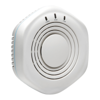
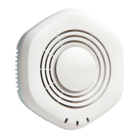
The Juniper Networks WLA321 and WLA322 are indoor, dual-band wireless LAN access points designed for ceiling installations. These devices facilitate wireless network connectivity within an indoor environment, supporting various wireless standards and configurations.
The WLA321 is equipped with one 2.4GHz/5GHz 2x2 IEEE 802.11n radio and two internal antennas, providing standard wireless access. The WLA322, on the other hand, features two radios: one 5GHz 2x2 IEEE 802.11n enhanced power radio and one standard power 2.4GHz radio, along with four internal antennas, offering broader coverage and potentially higher performance. Both models are primarily intended for ceiling mounting, although they can also be installed on a junction box on a wall with an optional kit.
The primary function of these access points is to provide wireless network access to client devices. They act as a bridge between wireless clients and the wired network, allowing users to connect to the internet or local network resources wirelessly. The dual-band capability means they can operate on both the 2.4 GHz and 5 GHz frequency bands, offering flexibility and helping to mitigate interference in crowded wireless environments. The 2.4 GHz band provides wider coverage, while the 5 GHz band offers higher data rates and less interference.
When connected to a wireless LAN controller (WLC), these access points become part of a larger managed wireless network. The WLC centralizes the management and configuration of multiple access points, simplifying network administration and enabling advanced features such as seamless roaming, security policies, and quality of service (QoS). The access points can be connected directly or indirectly to a WLC through an intermediate Layer 2 or Layer 3 network device.
Installation of the WLA321 and WLA322 access points is designed to be straightforward, primarily on a 9/16-inch or 15/16-inch T ceiling-tile rail. The process involves selecting an appropriate location under a recessed rail, cutting a hole in the ceiling tile for the Category 5 cable using a provided mounting template, and then running the cable through this hole.
The ceiling-mount bracket, included with the kit, is crucial for installation. It is designed with snaps that ensure the clips can fully extend to fit around the ceiling rail. The bracket is shipped in an open position, ready for immediate use. If it happens to be closed, users can open the snaps by pressing in and up with their thumbs on both sides of the snaps on the bottom of the bracket until it is fully open. Once the bracket clips are fully extended, they are aligned with the rail and hooked around the top sides. Pushing in on the sides of the bracket locks the clips over the rail, indicated by an audible click. It is important to verify that the bracket is securely locked by gently pulling down on it before proceeding with the access point installation.
After the bracket is secured, the Category 5 cable, extending from the ceiling, is plugged into the access point. The access point is then aligned with the bracket and pressed forward until it clicks into place, ensuring it is seated correctly. If the access point is not properly secured, a release button on top of the bracket can be pressed to unlock it, allowing for realignment and re-insertion.
For network connectivity, one end of the installed Category 5 cable is inserted into the Ethernet port of the access point, and the other end into the Ethernet port of the controller. The access point LED for the port on the controller provides visual feedback, indicating that the link is activated when it glows steadily green.
Configuration of the access point connection, especially for wireless LAN mesh or wireless bridge configurations, must be performed before deploying the access point in its final location. This configuration is typically done using the RingMaster GUI or the Mobility System Software CLI, as detailed in the Mobility System Software Configuration Guide.
While the manual primarily focuses on installation and initial setup, it does touch upon aspects related to security and proper handling, which contribute to the longevity and reliable operation of the device.
An optional security kit is available to secure the access point, which includes a security tool and a security screw. This screw is inserted into the release button on the access point using the provided tool to lock it into place. It is important not to overtighten the screw and to retain the security tool, as it is necessary to unlock and move the access point in the future. The use of power tools for inserting or removing the security screw is explicitly discouraged. This security feature helps prevent unauthorized removal or tampering with the access point.
The documentation emphasizes the importance of adhering to safety warnings to prevent personal injury or death. System administrators and equipment installers are responsible for the proper setup and operation of the WLAN system in accordance with all local rules and regulations. Users are advised to perform only the procedures described in the quick start guide and the comprehensive Wireless LAN Services (WLS) documentation. Before installing the WLC, it is crucial to review the planning instructions in the WLS documentation to ensure that the site meets power, environmental, and clearance requirements. These guidelines are essential for maintaining the device's operational integrity and ensuring a safe working environment.
For technical support, users are directed to the Juniper Networks support website, providing a resource for troubleshooting and assistance with any issues that may arise during the device's lifecycle. This ensures that users have access to expert help, contributing to effective maintenance and problem resolution.
| Brand | Juniper |
|---|---|
| Model | WLA322 |
| Category | Wireless Access Point |
| Language | English |