English
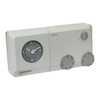
TR 200
13
Available languages:
When no more alterations are necessary
close the lid.
6.3 The “3
rd
operating level”or
“service level”
(Only for experts)
The “3
rd
operating level” or “service level” for
the expert becomes accessible when the con-
trol knob (n) is set to the position and the
button (q) is depressed for longer than 5
seconds. Non-existing values are left out.
With the button (q) the next parameter is
displayed. If the button is depressed again
when
Heating temp. +/– is displayed the “service
level” is left.
Note: It is important to know that the sen-
sors must not be influenced by ex-
ternal heating sources (body heat)
before calibration. As soon as the
lid is opened the measured values
of the sensors are recorded for cali-
bration.
In order to cancel a calibration, the cancel
button C (r) must be briefly depressed in the
“service level” when the respective value is
displayed. Now the original value is reactivat-
ed.
When no more alterations are necessary
close the lid.
6.4 Operating reserve
The time switch has an operating reserve of
approx. 2 hours after having been in continu-
ous operation for at least one day. In case of
a power failure the display is no longer func-
tioning. If the power supply returns within the
operating reserve, the display of the time, and
of the starting times for heating and economi-
cal operation returns.
Take care that the power supply is nev-
er interrupted for longer than 2 hours (do not
switch off the heating system in the summer
but select a low temperature at the regulator;
see chapter 6.1.2 tips for continuous heating).
6.5 Setting the summer and the standard
times
Proceed as described in the chapter “set-
ting the time”!
Do not alter the settings “start heating” and
“start economical operation”!
6.6 Brief operating instructions
The brief operating instructions where all im-
portant functions are briefly described are in
the compartment at the right side of the base
(illustration ).
6.7 Regulator with connected room tem-
perature sensor RF 1 (accessory)
If a room temperature sensor RF 1 is connect-
ed the built-in sensor in the regulator is inef-
fective. Now the temperature conditions sur-
rounding the external room temperature sen-
sor are decisive for temperature regulation.
Use the room temperature sensor RF1
when the mounting location of the regulator
has unfavourable measuring conditions which
are not applicable for the entire house e.g. in-
solation, a tiled stove nearby, etc.
• German/Deutsch • Turkish/Türkce
• English • Polish/Po polsku
• Dutch/Nederlands • Czech/cesky
• Spanish/Espanol • Slovak/slovensky
• Italian/Italiano • Hungarian/Magyar
• French/FRANCAIS • Slovenian/slovensko
• Portuguese/Portugues • Croatian/hrvatski
• Danish/Dansk • Lettish/Latviski
• Greek/ELLINIKA • Romanian/Romaneste
Display
example
Parameter
description
Setting
Room sensor +/–
21.3 °C
Calibrating the built-in
sensor
The dis-
played
value can
be altered
with the but-
ton “–” (o)
or “+” (p) in
steps of
0.1 K by
max. ±3 K
Rem. sensor +/–
21.4 °C
Calibrating the exter-
nal sensor (acces-
sory)
Econom. temp.+/–
14.6 °C
Calibrating the dis-
played value to scale
setting
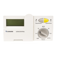
Control knob (m)
Heating temp.+/–
19.7 °C
Calibrating the dis-
played value to scale
setting
Control knob (k)
☞
Tip
2
☞
Tip
 Loading...