6 720 604 873-32.1O
1.
6 720 610 828 RO (02.01)
4 377-15.2O
1.3
226
protection on all connections and the original
supplied gaskets are placed.
B Select the aperture according to the
accessory documentation.
Fig. 7
Fig. 5
12
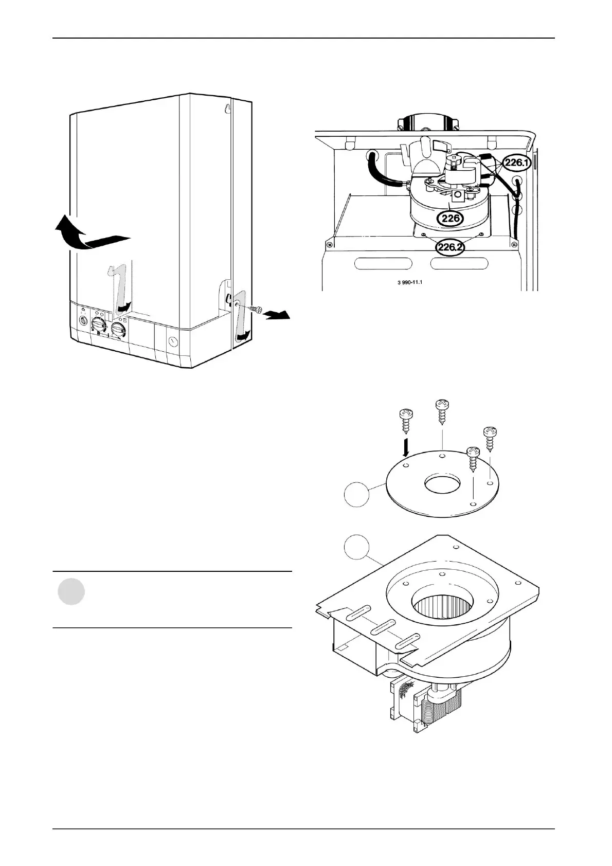
Catch preparation
B Remove the electrical connection (226.1) from
fan (226) and the corresponding rolling diaphragm
(1.3) is attached to the direction of absorption of the fan
(226).
B Check that the seals are in the correct
position, then tighten the pipe connections
with the Dutch nuts.
Installation of flue gas accessories
B Remove the combustion chamber cover.
ventilator.
Installing
B Remove the circulation screws
Attaching the appliance
B Place the appliance on the connection board.
B Set aside the cloak, pulling it forward.
B Lift the appliance and hang it on the rail.
B The boiler switches off.
B Take off your coat.
B All corks must be removed
Only aluminum pipes should be used
to prevent corrosion. The pipes must
be sealed.
B Remove the retaining screws (226.2) and remove the
fan (226).
Fig. 6
i
2.
2.
3.
Machine Translated by Google
 Loading...