hot water circuit (check pressure: max. 10 bar).
B Both deaerators open, the system is ventilated.
B Both deaerators close.
13
Water connections
B Check the final part of the exhaust pipe and the
wind protection and at the same time check the
free passage of the flue gas.
A manual deaerator 27.1 is mounted on the expansion
vessel and an automatic deaerator 27.2 is additionally
located on the pump .
B Attach the flue gas attachment.
B Check all boiler joints for leaks.
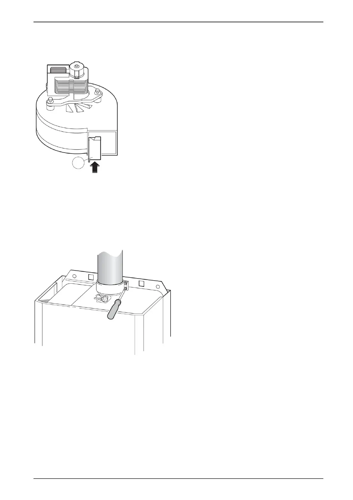
B Fit the corresponding reduction plate (1.7) to the
fan (226).
B Tighten the combustion chamber cover with the
screws.
Fig. 8
B Close the gas valve to protect the gas valve from
damage due to overpressure (maximum pressure
150 mbar).
B Depressurization is performed.
B Ventilate the appliance with the deaerator
B Refill the heating system to a pressure of 1 to
2 bar.
B Flow valves open and
B Open the cold water tap and fill
B Fill the heating system to a pressure of 1 to 2 bar.
B The flue gas accessory is provided.
Fig. 9
B Mount the housing and secure it with screws.
Ventilation of the heating system
Flue gas evacuation
B Check the gas system.
manual.
Installing
Gas pipeline
B Install the fan (226) in the boiler.
return the connection plate and fill the heating
system.
1.7
4873-30.1J
6 720 610 828 RO (02.01)
3.6 Checking the connections
Machine Translated by Google
 Loading...