.
Fig. 45
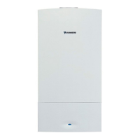
Display and key
Reinstalling the normal working mode
B Press the key
on the display appears
- - The key flashes.
B Remove the sealed cover (Fig. 41) from the two gas
adjusting screws.
The display and the key flash.
At dynamic pressures of methane gas below
18 or above 24 mbar, neither regulation nor
commissioning is permitted.
Dynamic inlet pressure
B Loosen the sealing screw (7) and attach the U-tube
pressure gauge to the measuring nozzle.
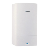
B Turn the thermostat knob until 2. (= maximum rated
thermal output (domestic hot water)) appears on the
display).
Fig. 44
Nozzle pressure at minimum useful thermal power
Fig. 47
B Check the pressure in dynamic mode.
B Check the set values min. and max. and, if necessary,
correct them.
blink.
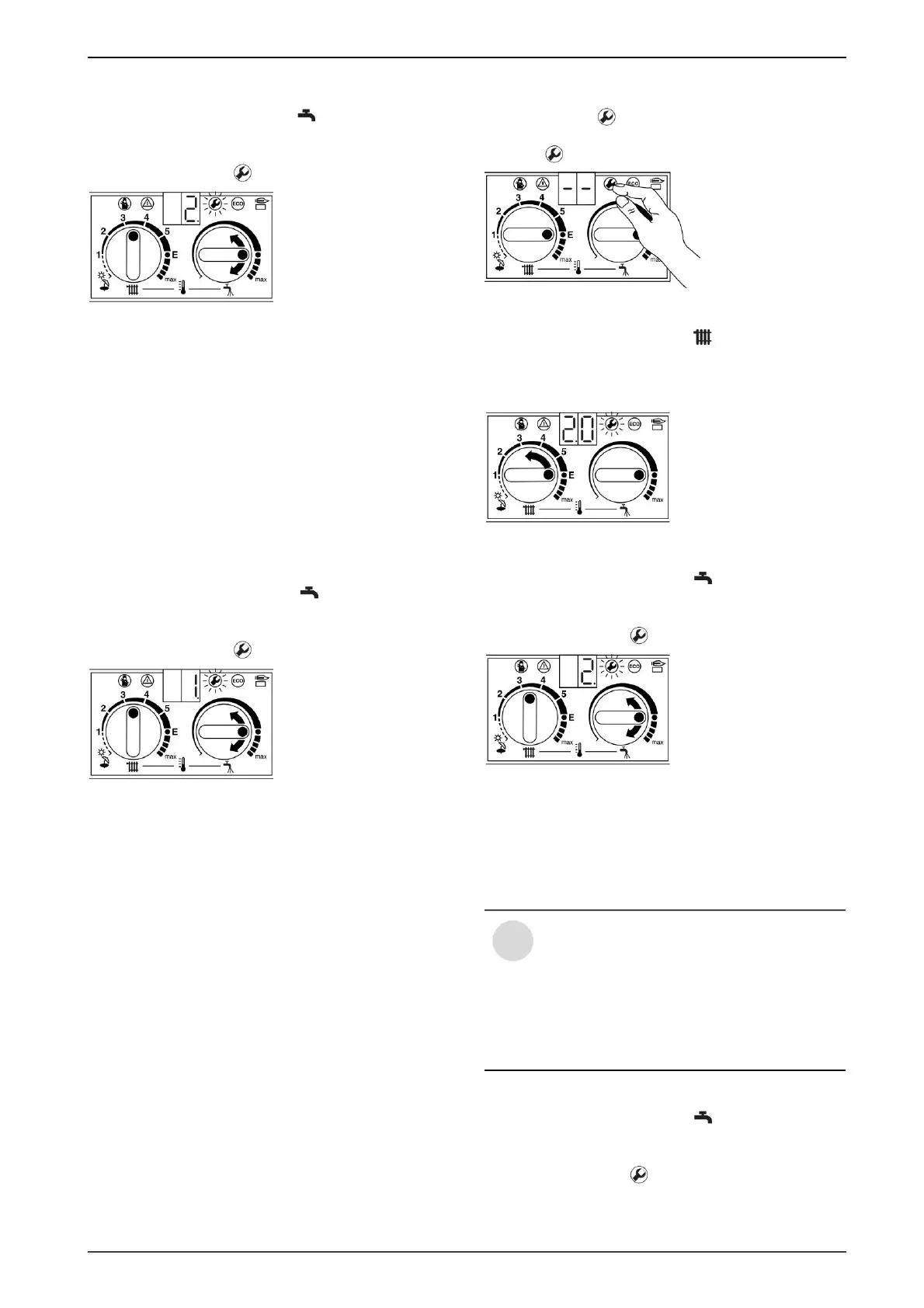
B Turn the thermostat knob until 2.0 appears on the
display.
“Max” at the nozzle (mbar). Adjust the nozzle pressure
with the adjusting screw (63). Turning to the right means
more gas, and turning to the left means less gas.
blink.
B Extract the pressure from the table on page 34
B Turn the thermostat knob all the way to the left until 0. (=
normal operating mode) appears on the display.
and keep it that way until
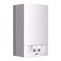
B Turn the thermostat knob counterclockwise until 1. (= min.
Useful heat output) appears on the display.
The cause must first be detected and then
the anomaly remedied. If this is not possible,
the gas supply to the plant is stopped and
the Gas Distribution Authority is notified.
B Extract the pressure from the table on page 34
B Open the gas valve and switch on the boiler.
The display and the key flash.
B Loosen the sealing screw (3) and attach the U-tube
pressure gauge to the measuring nozzle.
B Turn the thermostat knob until 2. (= maximum rated
thermal output (domestic hot water)) appears on the
display).
- for methane gas it must be between 18 and 24 mbar. -
the LPG must be the one on the appliance label.
Fig. 48
B Switch off the boiler, close the gas valve, remove the U-
tube pressure gauge and tighten the sealing screw (3).
27
Gas adjustment, depending on its type
After a short time, the display will show the stored
operating mode (0. = normal operating mode).
(Domestic hot water)
Fig. 46
“Min (domestic hot water)” at the nozzles (mbar). Adjust
the nozzle pressure with the adjusting screw (64).
Display and key
i
6 720 610 828 RO (02.01)
6 720 610 332-61.1O
6 720 610 332-61.1O
6 720 610 332-32.1O
6 720 610 332-63.1O
6 720 610 332-60.1O
Machine Translated by Google
 Loading...