.
B Loosen the sealing screw (3) and attach the U-tube
pressure gauge to the measuring nozzle.
Fig. 52
B Loosen the sealing screw (7) and attach the U-tube
pressure gauge to the measuring nozzle.
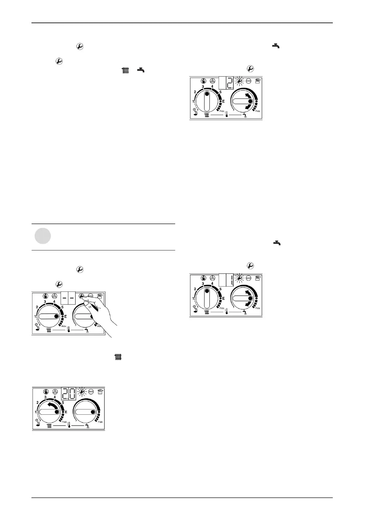
B Turn the thermostat knob until 2. (= maximum rated
thermal output (domestic hot water)) appears on the
display).
Flow rate at minimum useful thermal power
.
Dynamic inlet pressure
B Press the key
on the display appears
- - The key flashes.
B Switch off the boiler, close the gas valve, remove the U-
tube pressure gauge and tighten the sealing screw (7).
7.1.3 Volumetric method
B The values of the Wobbe index (WO), the calorific value
(PC) and the lower calorific value (PCI) of the gas must
be requested from the Local Gas Distribution Authority.
Flow rate at maximum useful thermal power
B Press the key
on the display appears
- - The key flashes.
B Turn the thermostat knob until 2.0 appears on the
display.
Fig. 50
The display shows the flow temperature again.
B Turn the thermostat knobs to the values as well
B Remove the sealed cover (Fig. 41) from the two gas
adjusting screws.
B Turn the thermostat knob counterclockwise until 1. (= min.
Useful heat output) appears on the display.
B Extract the “min (domestic hot water)” gas flow (l / min)
from the table on page 35. Adjust the nozzle pressure
with the adjusting screw (64).
B Open the gas valve and switch on the boiler.
Fig. 51
(Domestic hot water)
The display and the key flash.
B Switch off the boiler and close the gas valve.
and keep it that way until
B Replace the cover over the gas adjusting screws and seal
it.
In order to be able to make the
adjustment, the boiler must be operated for
more than 5 minutes.
and keep it that way until
blink.
After a short time, the display will show the stored
operating mode (0. = normal operating mode).
B Check the set values min. and max. and, if necessary,
correct them.
28
Gas adjustment, depending on its type
B If you are dissatisfied with the shape or color of the flame,
check the nozzles.
B Extract the “max” gas flow (l / min) from the table on page
35. Adjust the nozzle pressure with the adjusting screw
(63) following the instructions on the gas meter. Turning
to the right means more gas, and turning to the left means
less gas.
Display and key
When refueling with a LPG / air mixture, during the
maximum consumption time, the regulation must be checked
using the nozzle pressure method.
initials.
Fig. 49
i
6 720 610 828 RO (02.01)
6 720 610 332-63.1O
6 720 610 332-60.1O
6 720 610 332-32.1O
6 720 610 332-61.1O
Machine Translated by Google
 Loading...