4.1. Checking upon receipt
• When the goods are delivered, make sure that all parts listed on
the delivery note are in perfect condition and have suffered no damage
during shipping.
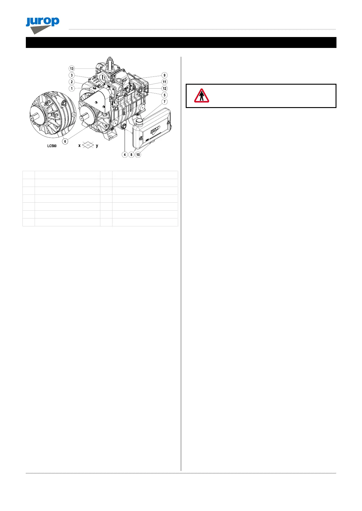
• Make sure the vacuum pump has its identification plate affixed on
the front cover. Pumps without such identification are to be considered
anonymous and potentially dangerous: in such an event, they must not
be used, otherwise the manufacturer will be deemed free from any
liability whatsoever.
4.2. Storing in the warehouse
• If the pump will not be installed inside a short time after delivery:
− Remove the guards from the ports and spray a film of protective oil
over the inner surfaces of the body, rotors and sides. Then attach
again the guards;
− Store in a closed and dry place. Renew the preserving oil
periodically.
• To temporarily store a used pump, follow the instructions below:
− Thoroughly clean the pump.
− Equip the pump with suitable anti-corrosion protection.
4.3. Handling and installation
• Before each movement, verify that the lifting equipment has a
suitable capacity (check the weight of the decompressor, possibly
showed in this manual, in the paragraph 2.1).
• Do not lift the packaging or the machine when moving more than
50 cm from the ground. Proceed with the final lifting only near the
installation point.
• Harness the machine with suitable straps / chains near the main
body, paying attention to the position of the mass centre of gravity to
ensure the load stability.
4.4. Mounting
• The pump must be assembled for an easy access for maintenance
operations and secured rigidly to a frame or levelled base (max. 3°
slant to the horizontal plane. See Fig. 4.1). The base must be such as
to avoid vibrations, bending or deformation.
• Where possible, we recommend the use of vibration dampers
between the support points of the machine and the base housing it.
• Leave enough space around the pump to allow the free circulation
of air for cooling; avoid exposure to dirt and debris.
• Prepare the necessary space for an easy access to the lubrication
check-points (tank level and gear box, oilers) and to the oil tank filling
port, the four-way manifold handle, and the vane wear inspection ports.
• Provide for suitable manoeuvring spaces of the inverter lever. The
control lever has two possible switching positions well defined by the
latches and numbers reported on the fusion. It is directly connected to
the internal diverter tang of the inverter, making it very intuitive: 90° of
the lever switching corresponds to 90° of the inverter switching.
• Based on the functionality of the system which will house the
decompressor, the designer of the end machine, must:
− Properly signal the functionality of the inverter according to the
position of the manual operating lever or of the pneumatic actuator
or of the hydraulic one.
− Install suitable pressure and / or vacuum restrainer valves near the
inlet and outlet points of the machine.
• In case of LC with hydraulic motor, provide the necessary space to
disassemble the motor itself and proceed with joint lubrication.
• In the event that the decompressor is electrically isolated, connect
it to the ground or make it equipotential with the housing machine.
Check that the paint does not prevent its passage.
• The machine expels gas during delivery at temperatures that can
reach the maximum permitted values for operation, with its lubricating
oil in suspension. Oil consumption is stated in paragraph 2.3, the
quantity of consumed oil corresponds to the quantity of oil emitted at
delivery.
• The installer will have to provide an appropriate delivery oil
separator (such as the JUROP cyclone silencer-oil separator supplied
on request) and/or direct the flow to the drain in an area that is not at
risk.
• The belt transmission guard of the coolant recirculation pump
supplied by Jurop is partial and must be completed/integrated with the
guard of the main transmission provided by the installer. If the
transmissions are accessible by the operator, protect them with a fixed
or interlocked guard and signal them with appropriate pictograms.
 Loading...