REV
02-12-2019
INSTALLATION
,
USE AND MAINTENANCE MANUAL
–
PNR/E 73-83-104-124
–
PNR 142
11 / 44
Via Crosera n° 50
33082 Azzano Decimo, PN (Italia)
EL
AX
http://www.jurop.it
e-mail: info@jurop.it
4.5. Mounting
• The pump must be assembled for an easy access for maintenance
operations and secured rigidly to a frame or levelled base (max. 3°
slant to the horizontal plane. See Fig. 4.1). The base must be such as
to avoid vibrations, bending or deformation.
• It is recommended to install the pump on vibration adsorbing pads
to reduce the noise and vibrations produced during its operation.
• Leave enough space around the pump to allow the free circulation
of air for cooling; avoid exposure to dirt and debris.
• Provide the necessary space to reach all points of lubrication
control (oil level), and the oil tank filler cap, the lever of the 4-way
switch, vanes inspection ports. See Pic. 4.1.
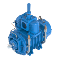
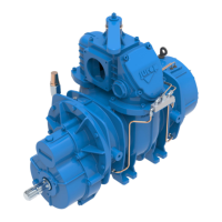
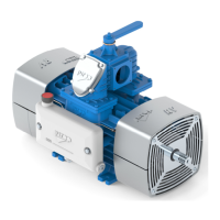
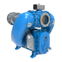
• For PNR/PNE 73-83-104-124 the oil tank is mounted on the rear
side of the pump. Instead for PNR142 the oil tank is mounted on the
suction side of the housing.
• Provide for suitable manoeuvring spaces of the inverter lever. The
control lever has two possible switching positions well defined by the
latches and numbers reported on the fusion. It is directly connected to
the internal diverter tang of the inverter, making it very intuitive: 90° of
the lever switching corresponds to 90° of the inverter switching.
• Based on the functionality of the system which will house the
decompressor, the designer of the end machine, must:
- Properly signal the functionality of the inverter according to the
position of the manual operating lever or of the pneumatic
actuator or of the hydraulic one.
- Install suitable pressure and / or vacuum restrainer valves near
the inlet and outlet points of the machine.
• In case of PNR/PNE with hydraulic motor, provide the necessary
space to disassemble the motor itself and proceed with joint lubrication.
• In the event that the decompressor is electrically isolated, connect
it to the ground or make it equipotential with the housing machine.
Check that the paint does not prevent its passage.
• The machine expels gas during delivery at temperatures that can
reach the maximum permitted values for operation, with its lubricating
oil in suspension. Oil consumption is stated in paragraph 2.2, the
quantity of consumed oil corresponds to the quantity of oil emitted at
delivery.
4.6. Vacuum / Pressure line
• See the following picture.
• The hoses connecting the suction and exhaust ports of the
vacuum pump must be of adeguate diameter (suggested not less than
3”) and of oil and corrosion resistant materials and before connecting
them, make sure that they are perfectly clean in the inside.
• The weight or dimensions of the pipes must in no way stress the
PNR/PNE body. Use high temperature resistant rubber sleeves.
• Remove the port guards when mounting. The pipes and
components of the whole line must be clean.
• Avoid constrictions and tight curves where they are not essential.
• Connect the pump to the tank through the suction manifold which
has a threaded port for fitting the over-pressure valve.
Pic. 4.2
Vacuum / Pressure line components
1. Primary shutoff
2. Secondary shutoff
3. Suction filter
4.
Silencer /
5. Over-pressure safety relief valve
6. Vacuum control valve
• The exhaust pipes can reach high temperatures. Protect those
adequately from the operator reach.
• A clapet valve on suction pipe avoids rotation in the opposite
direction when the pump stops.
• To avoid that foreign liquids will enter the vacuum pump it is
necessary to mount on the suction line an over-flow valve of “floating-
ball” type (Fig. 4.2. - pos. 1). The flow section of this valve must be
equivalent to the suction hose’s one.
• It is also necessary to have on the line a suitable air filter for
preventing solids to be sucked inside the vacuum pump. It is also
recommended to mount a “secondary shutoff” of floating-ball type (Fig.
4.2 - pos. 2) between vacuum pump and over-flow (primary shutoff),
along with the previously mentioned air filter (Fig. 4.2 - pos. 3).
• Called also 4-way valve, normally is manually operated but it can
be at any time transformed in pneumatically or hydraulic operated upon
request of the appropriate kit.
• During normal running of the pump the resulting noise should be
reduced by means of a suitable silencer (Fig. 4.2 - pos. 4) mounted as
close as possible to the pump itself. It has to be dimensioned for the air
flow produced by the pump model. The oil used for the pump’s inside
lubrication has to be separated from the exhausted air by means of an
adequate oil-separator, placed directly inside the silencer. The silencer
is fitted also with a draining tap for the collected oil and condensed
liquids.
 Loading...