EasyManua.ls Logo

JVC AV-14FR10 - User Manual

JVC AV-14FR10
72 pages
Print Icon
To Next Page IconTo Next Page
Loading...
No.51865
Nov. 2000
AV-14FR10/AV-14F10
AV-1434TEE/AV-1434EE
AV-14FTT2/AV-14FTG2
1
COPYRIGHT © 2001 VICTOR COMPANY OF JAPAN, LTD.
Nov. 2001
AV-14FR10/AV-14F10
AV-1434TEE/AV-1434EE
AV-14FTT2/AV-14FTG2
/-A
CONTENTS
!
SPECIFICATIONS
・・・・・・・・・・・・・・・・・・・・・・・・・・・・・・・・
・・・・・・・・・・・・・・・・・・・・・・・・・・・・・・・・・・・・・・・・・・・・・・・・・・・・・・・・・・・・・・・・
・・・・・・・・・・・・・・・・・・・・・・・・・・・・・・・・・・・・・・・・・・・・・・・・・・・・・・・・・・・・・
・・・・・・・・・・・・・・・・・・・・・・・・・・・・・・・・・・・・・・・・・・・・・・・・・・・・・・・・・・
・・・・・・・・・・・・・・・・・・・・・・・・・・・・・
2
!
SAFETY PRECAUTIONS
・・・・・・・・・・・・・・・・・・・・・・・・・・・・・・・・
・・・・・・・・・・・・・・・・・・・・・・・・・・・・・・・・・・・・・・・・・・・・・・・・・・・・・・・・・・・・・・・・
・・・・・・・・・・・・・・・・・・・・・・・・・・・・・・・・・・・・・・・・・・・・・・・・・・・・・・・
・・・・・・・・・・・・・・・・・・・・・・・・・・・・・・・・・・・・・・・・・・・・・・
・・・・・・・・・・・・・・・・・・・・・・・
3
!
FEATURES
・・・・・・・・・・・・・・・・・・・・・・・・・・・・・・・・
・・・・・・・・・・・・・・・・・・・・・・・・・・・・・・・・・・・・・・・・・・・・・・・・・・・・・・・・・・・・・・・・
・・・・・・・・・・・・・・・・・・・・・・・・・・・・・・・・・・・・・・・・・・・・・・・・・・・・・・・・・・・・・・・・
・・・・・・・・・・・・・・・・・・・・・・・・・・・・・・・・・・・・・・・・・・・・・・・・・・・・・・・・・・・・・・・・
・・・・・・・・・・・・・・・・・・・・・・・・・・・・・・・・・・・
・・・・・・
・・・
4
!
MAIN DIFFERENCE LIST
・・・・・・・・・・・・・・・・・・・・・・・・・・・・・・・・
・・・・・・・・・・・・・・・・・・・・・・・・・・・・・・・・・・・・・・・・・・・・・・・・・・・・・・・・・・・・・・・・
・・・・・・・・・・・・・・・・・・・・・・・・・・・・・・・・・・・・・・・・・・・・・・・・・・・・・・・
・・・・・・・・・・・・・・・・・・・・・・・・・・・・・・・・・・・・・・・・・・・・・・
・・・・・・・・・・・・・・・・・・・・・・・
5
!
FUNCTIONS
・・・・・・・・・・・・・・・・・・・・・・・・・・・・・・・・
・・・・・・・・・・・・・・・・・・・・・・・・・・・・・・・・・・・・・・・・・・・・・・・・・・・・・・・・・・・・・・・・
・・・・・・・・・・・・・・・・・・・・・・・・・・・・・・・・・・・・・・・・・・・・・・・・・・・・・・・・・・・・・・・・
・・・・・・・・・・・・・・・・・・・・・・・・・・・・・・・・・・・・・・・・・・・・・・・・・・・・・・・・・・・・・・・・
・・・・・・・・・・・・・・・・・・・・・・・・・・・・・・・・・・
・・・・
・・
6
!
SPECIFIC SERVICE INSTRUCTIONS
・・・・・・・・・・・・・・・・・・・・・・・・・・・・・・・・
・・・・・・・・・・・・・・・・・・・・・・・・・・・・・・・・・・・・・・・・・・・・・・・・・・・・・・・・・・・・・・・・
・・・・・・・・・・・・・・・・・・・・・・・・・・・・・・・・・・・・・・・・・・・・・
・・・・・・・・・・・・・・・・・・・・・・・・・・
・・・・・・・・・・・・・
8
!
SERVICE ADJUSTMENTS
・・・・・・・・・・・・・・・・・・・・・・・・・・・・・・・・
・・・・・・・・・・・・・・・・・・・・・・・・・・・・・・・・・・・・・・・・・・・・・・・・・・・・・・・・・・・・・・・・
・・・・・・・・・・・・・・・・・・・・・・・・・・・・・・・・・・・・・・・・・・・・・・・・・・・・・
・・・・・・・・・・・・・・・・・・・・・・・・・・・・・・・・・・・・・・・・・・
・・・・・・・・・・・・・・・・・・・・・
15
!
PARTS LIST
・・・・・・・・・・・・・・・・・・・・・・・・・・・・・・・・
・・・・・・・・・・・・・・・・・・・・・・・・・・・・・・・・・・・・・・・・・・・・・・・・・・・・・・・・・・・・・・・・
・・・・・・・・・・・・・・・・・・・・・・・・・・・・・・・・・・・・・・・・・・・・・・・・・・・・・・・・・・・・・・・・
・・・・・・・・・・・・・・・・・・・・・・・・・・・・・・・・・・・・・・・・・・・・・・・・・・・・・・・・・・・・・・・・
・・・・・・・・・・・・・・・・・・・・・・・・・・・・・・・・・
33
OPERATING INSTRUCTIONS
STANDARD CIRCUIT DIAGRAM
・・・・・・・・・・・・・・・・・・・・・・・・・・・・・・・・
・・・・・・・・・・・・・・・・・・・・・・・・・・・・・・・・・・・・・・・・・・・・・・・・・・・・・・・・・・・・・・・・
・・・・・・・・・・・・・・・・・・・・・・・・・・・・・・・・・・・・・・・・・・・・・・・・
・・・・・・・・・・・・・・・・・・・・・・・・・・・・・・・・
・・・・・・・・・・・・・・・・
2-1
BASIC CHASSIS
CG
SERVICE MANUAL
COLOUR TELEVISION
[ RM-C364GY ][ RM-C90 ]
Question and Answer IconNeed help?

Do you have a question about the JVC AV-14FR10 and is the answer not in the manual?

Overview

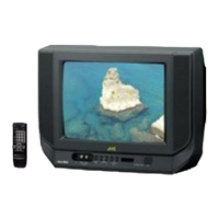
This document is a service manual for JVC colour televisions, specifically models AV-14FR10, AV-14F10, AV-1434TEE, AV-1434EE, AV-14FTT2, and AV-14FTG2.

Function Description

The JVC colour televisions covered by this manual are designed for interactive on-screen control, offering a range of features for user convenience and picture optimization. They include a wide range voltage AC power input, supporting 110V to 240V for AV-14FTT2 and AV-14FTG2/-A models. The televisions are equipped with AUDIO/VIDEO INPUT and OUTPUT terminals, allowing for connectivity with external devices.

A MUTING button provides instant audio reduction to zero. The functional remote control unit enables comprehensive operation of the TV set, including channel selection, volume control, and power ON/OFF. The internal architecture utilizes I2C bus control with single-chip ICs for IF, V/C, DEF, VSM PRESET, PRESET, and TURBO TIMER functions.

An "AUTO PROGRAM" feature allows for automatic selection of TV stations and rearrangement of channels. For models AV-14FR10, AV-1434TEE, and AV-14FTT2, a built-in FASTEXT/WST system provides teletext capabilities. The televisions also incorporate an "ECO MODE" (ECONOMY, ECOLOGY) that automatically adjusts picture brightness and contrast based on ambient room light, aiming for optimal and eye-friendly viewing. Additional built-in features include an ON TIMER, RETURN+, and CHILD LOCK.

Important Technical Specifications

Dimensions (W×H×D) and Mass: All models share the same physical dimensions: 462mm × 340.5mm × 375mm, with a mass of 10kg.

TV RF System: Supports B/G, I, D/K, K1 standards.

Colour System:

  • RF Mode: PAL/SECAM
  • VIDEO Mode: PAL/SECAM/NTSC3.58/NTSC4.43

Teletext System:

  • AV-14FR10/AV-1434TEE/AV-14FTT2: FLOF (UK system) and WST (world standard system)
  • AV-14F10/AV-1434EE/AV-14FTG2/-A: WST (world standard system)

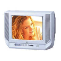
Picture Tube: Visible size: 34cm measured diagonally.

High Voltage: 22.5kV ± 1.5kV (at zero beam current).

Receiving Frequency:

  • VHF (VL): 43.75MHz ~ 155.75MHz
  • VHF (VH): 155.78MHz ~ 466.25MHz
  • UHF: 466.28MHz ~ 864.75MHz
  • CATV: Cable TVs of Mid (X-Z, S1-S10), Super (S11-S20), and Hyper (S21-S41) bands receivable.

Intermediate Frequency:

  • VIF Carrier: 38.0MHz
  • SIF Carrier: 32.5MHz (5.5MHz), 31.5MHz (6.5MHz), 32.0MHz (6.0MHz)

Colour Sub Carrier Frequency:

  • PAL (4.43MHz)
  • SECAM (4.40625MHz / 4.25MHz)
  • NTSC (3.58MHz / 4.43MHz)

Power Input:

  • AV-14FR10/AV-1434TEE/AV-14F10/AV-1434EE: AC220~240V, 50/60Hz
  • AV-14FTT2/AV-14FTG2/-A: AC110~240V, 50/60Hz

Power Consumption: 68W (Max) / 47W (Avg.)

Speaker: 5cm × 9cm, Oval type × 2 (2W monaural).

Aerial Input Terminal: 75Ω Unbalanced.

Input Terminals:

  • Video: 1V(p-p), 75Ω, RCA × 2 (Front/Rear)
  • Audio: 500mV(rms) (-4dBs), High impedance, RCA × 2 (Front/Rear)

Output Terminals:

  • Video: 1V(p-p), 75Ω, RCA × 1
  • Audio: 500mV(rms) (-4dBs), Low impedance, RCA × 1

Headphone Jack: 3.5mm mini jack.

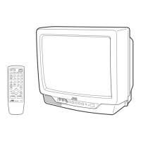
Remote Control Unit:

  • AV-14FR10/AV-1434TEE/AV-14FTT2: RM-C90 (Battery size: AA/R06/UM-3 × 2)
  • AV-14F10/AV-1434EE/AV-14FTG2/-A: RM-C364GY (Battery size: AA/R06/UN-3 × 2)

Usage Features

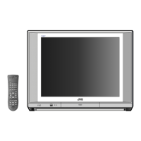
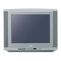
The televisions offer a user-friendly interface with both front panel controls and a remote control unit.
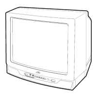
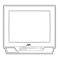
Front Panel:

  • MENU buttons
  • CHANNEL -/+ buttons
  • VOLUME -/+ buttons
  • ECO sensor
  • REMOTE CONTROL sensor
  • ON TIMER lamp
  • POWER lamp
  • MAIN POWER button
  • A/V INPUT terminal
  • HEADPHONE jack

Rear Panel:

  • ANT Terminal
  • VIDEO INPUT Terminal
  • VIDEO OUTPUT Terminal
  • AUDIO INPUT Terminal
  • AUDIO OUTPUT Terminal

Remote Control Unit (RM-C90 / RM-C364GY): Both remote control units provide similar functionalities, including:

  • ECO SENSOR key
  • COLOUR SYSTEM key
  • SOUND SYSTEM key
  • DISPLAY key
  • TV/VIDEO key
  • OFF TIMER key
  • PICTURE MODE key
  • CHANNEL SCAN key
  • RETURN+ key
  • CHANNEL -/+ key
  • POWER key
  • MUTING key
  • TV/TEXT key
  • MENU keys (up/down/left/right)
  • Number (CH.) keys
  • VOLUME -/+ key
  • Teletext key (RM-C90 only)

Maintenance Features

The service manual provides detailed instructions for maintenance and adjustment.

Disassembly Procedure:

  • Removing the Rear Cover: Involves unplugging the power, removing specific screws, and withdrawing the cover.
  • Removing the Main PW Board: Requires removing the rear cover, gently raising the board sides, detaching the PWB stopper, and withdrawing the board (disconnecting wire clamps/connectors as needed).
  • Removing the Speaker: Involves removing the rear cover and specific screws.

Checking the Main PW Board: Instructions for pulling out and erecting the Main PW Board vertically for inspection, with cautions against contact with other parts and ensuring proper CRT earth wire and connector connections before powering on.

Wire Clamping and Cable Tying: Emphasizes the importance of clamping wires and using new cable ties if existing ones are inadvertently removed.

Replacement of Memory ICs:

  • Procedure: Power off, replace ICs with those written with initial data values, power on, and then check and set the SYSTEM CONSTANT SET via a specific sequence of remote control button presses (DISPLAY + PICTURE MODE). This process involves navigating a SERVICE MENU to verify and adjust settings if necessary, followed by user settings and service menu verification.
  • Note: The functions of the RM-C90 and RM-C364GY remote control units are the same despite different key positions.

Replacement of IC301 (IF V/C DECODER):

  • Procedure: Turn power off, replace IC301 with a new one, and then simultaneously press the MENU and VOL+ buttons on the front cabinet while turning the power on. This writes data to the micro-computer.

Service Adjustment:

  • General Instructions: Adjustments can be made via the remote control unit or conventional methods. Initial setting values are provided as a baseline, but optimal screen conditions may require different values. A warm-up period of at least 30 minutes is recommended before adjustments. Specific measuring instruments (DC voltmeter, oscilloscope, signal generator) and fixtures are required.
  • User Mode Position Presets: Before adjustment, functions like PICTURE MODE, VNR, TINT/COLOUR/BRIGHT/CONT./SHARP, BLUE BACK, OFF TIMER, ECO SENSOR, and AUTO SHUT OFF should be set to their default states (BRIGHT, OFF, CENTER, OFF, OFF, OFF, OFF respectively).
  • Adjustment Items: Includes B1 POWER SUPPLY, FOCUS adjustment, IF circuit adjustment, V/C (Video/Chroma) circuit adjustment, DEFLECTION circuit adjustment, VSM PRESET setting, and PURITY/CONVERGENCE adjustment.

Basic Operation of Service Menu:

  • Adjustment Items: Covers IF, V/C, DEF, VSM PRESET, PRESET, and TURBO TIMER.
  • Navigation: Enter the SERVICE MENU by pressing DISPLAY and PICTURE MODE simultaneously. Exit by pressing DISPLAY twice. Select items using number keys (1-6) and adjust values using MENU up/down/left/right keys.

Replacement of Chip Components:

  • Cautions: Avoid heating for more than 3 seconds, do not rub electrodes or resist parts, melt solder adequately, and do not reuse chip parts.
  • Soldering Iron: Use a high-insulation soldering iron with a thin pointed end (30W recommended).
  • Removal Steps: For resistors, capacitors, etc., push the part with tweezers and alternately melt solder at each end. For transistors, diodes, etc., apply extra solder to each lead, then push and melt solder alternately.
  • Installation Steps: Apply solder to the pattern, grasp the chip part with tweezers, place it on the solder, and then heat/melt solder at both ends. For transistors, diodes, etc., apply solder to the pattern, grasp the chip part, place it on the solder, solder lead A first, then leads B and C.

JVC AV-14FR10 Specifications

General IconGeneral
BrandJVC
ModelAV-14FR10
CategoryTV
LanguageEnglish

Related product manuals