No. 52061 9
AV-29WS3 AV-29WX3
AV-29WH3 AV-2978TEE
REPLACEMENT OF MEMORY IC
1. MEMORY IC
This TV uses the following memory IC.
Memory IC: IC1702 on MAIN PW Board
The memory IC memorizes data for correctly operating the video
and deflection circuits. When replacing the memory IC, be sure to
use the same type IC written with the initial values of data. In other
words, use the specific IC listed in “PRINTED WIRING BOARD
PARTS LIST”. For its mounting location, refer to “ADJUSTMENT
LOCATIONS”.
2. PROCEDURE FOR REPLACING MEMORY IC
(1) Power off
Switch the power off and unplug the power cord from the wall
outlet.
(2) Replacing the memory IC
Replace the memory IC with new one. Be sure to use the memory
IC written with the initial data values.
(3) Power on
Plug the power cord into the wall outlet and switch the power on.
(4) Check and setting of SYSTEM CONSTANT SET:
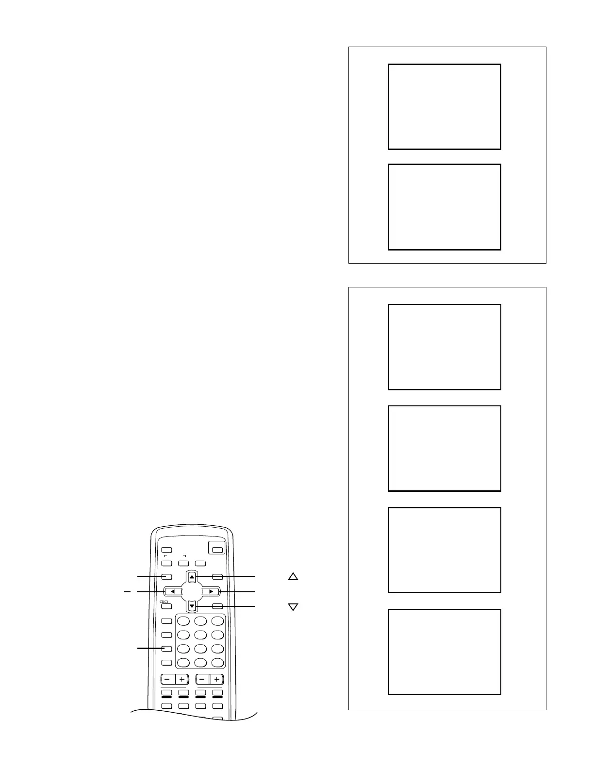
1) Press the DISPLAY key and the PICTURE MODE key on the
remote control unit simultaneously.
The SERVICE MENU screen will be displayed.(See Fig.1.)
2) In the SERVICE MENU, press the DISPLAY key and PIC-
TURE MODE key simultaneously. Then, the SYSTEM CON-
STANT SET screen will be displayed.(See Fig.2.)
3) Check whether the setting values of the SYSTEM CONSTANT
SET are the same as those indicated in Table1.
If the value is different, select the setting item with the MENU
&/^ key, and set the correct value with the MENU
*/T
key.
4) Press the DISPLAY key twice to return to the normal screen.
(5) Receive channel setting
Refer to the OPERATING INSTRUCTIONS and set the receive
channels (channels preset).
(6) User setting
Check the user setting values in Table 2, and if setting value is
different, set the correct value.
For setting, refer to the OPERATING INSTRUCTIONS.
(7) Setting of SERVICE MENU
Verify the setting for each setting item in the SERVICE
MENU.(See Table 3.) If readjustment is necessary, perform ad-
justment referring to “SERVICE ADJUSTMENTS”.
NAME OF REMOTE CONTROL KEYS
1. IF
3. DEF
5. PRESET
7. PLUG & PLAY (ON)
2. VC
6. A2NICAM
4. VSM PRESET
SERVICE MENU
SERVICE MENU
1-7 : SELECT DISPLAY : EXIT
[AV-29WS3, AV-29WS3
/AU
, AV-29WH3]
******* **** ***** *****
**** **** *** ***
1. IF
3. DEF
5. PRESET
6. PLUG & PLAY (ON)
2. VC
4. VSM PRESET
SERVICE MENU
1-6 : SELECT DISPLAY : EXIT
[AV-29WX3, AV-29WX3
/A
,AV-2978TEE]
******* **** ***** *****
**** **** *** ***
Fig. 1
Fig. 2
MUTING
OFF
TIMER
ECO
SENSOR
PICTURE
MODE
CHANNEL
SCAN
REVEAL
SUBPAGE CANCEL
TEXT
HOLD INDEX
STORE MODE
SIZE
SYSTEM
COLOUR SOUND
CINEMA
SURROUND
MENU
CHANNEL
RETURN+
POWER
DISPLAY
I
/
II
TV/TEXT
TV/VIDEO
VOLUME
123
456
789
0
-
/
--
MENU
MENU
MENU
+
DISPLAY
MENU
PICTURE
MODE
SYSTEM CONSTANT-
Ι
>? : SEL
-
+ : OPE
COMB
TILT
MULTI
YES
YES
TEXT
ERCMI
SUPER BASS
YES
LANGUAGE
E/R/C/M/I
SYSTEM CONSTANT SET 1
SYSTEM
DISP : EXIT
SYSTEM CONSTANT-
II
>? : SEL
-
+ : OPE
B / B SOUND
YES
NO
TUNER
MU
COLOUR AUTO
YES
BILINGUAL
YES
SYSTEM CONSTANT SET 2
MSP
DISP : EXIT
SYSTEM CONSTANT-
III
>? : SEL
-
+ : OPE
: 040
: 040
SYSTEM CONSTANT SET 3
LOCK 1 MHz
500 KHz
: 040
250 KHz
: 030
156. 25 KHz
: 030
31.25 KHz
DISP : EXIT
SYSTEM CONSTANT-
IV
>? : SEL
-
+ : OPE
YES
YES
SYSTEM CONSTANT SET 4
3D SURROUND
NO
3CH VOL/TONE
AMP TUNER
DISP : EXIT
 Loading...