EasyManua.ls Logo

JVC AV-21MT16/Z User Manual

JVC AV-21MT16/Z
122 pages
To Next Page IconTo Next Page
Page #1 background imageLoading...
Page #1 background image
SERVICE MANUAL
COPYRIGHT © 2006 Victor Company of Japan, Limited
No.YA405
2006/7
FLAT COLOR TELEVISION
YA40520067
AV-21MT16/Z, AV-21MT36/Z,
AV-25MT16
/Z, AV-29MT16/Z,
AV-29MT36
/Z
TABLE OF CONTENTS
1 PRECAUTION. . . . . . . . . . . . . . . . . . . . . . . . . . . . . . . . . . . . . . . . . . . . . . . . . . . . . . . . . . . . . . . . . . . . . . . . . 1-3
2 SPECIFIC SERVICE INSTRUCTIONS . . . . . . . . . . . . . . . . . . . . . . . . . . . . . . . . . . . . . . . . . . . . . . . . . . . . . . 1-4
3 DISASSEMBLY . . . . . . . . . . . . . . . . . . . . . . . . . . . . . . . . . . . . . . . . . . . . . . . . . . . . . . . . . . . . . . . . . . . . . . . 1-6
4 ADJUSTMENT . . . . . . . . . . . . . . . . . . . . . . . . . . . . . . . . . . . . . . . . . . . . . . . . . . . . . . . . . . . . . . . . . . . . . . . 1-16
5 TROUBLESHOOTING . . . . . . . . . . . . . . . . . . . . . . . . . . . . . . . . . . . . . . . . . . . . . . . . . . . . . . . . . . . . . . . . . 1-41
BASIC CHASSIS
CW2
[AV-21MT16/Z, AV-21MT36/Z] [AV-25MT16/Z] [AV-29MT16/Z, AV-29MT36/Z]
POWER
EXIT
CLOSED
CAPTION
VNR
ECO
CINEMA
SURROUND
BASS
RM-C1287
100+
COLOR

Table of Contents

Question and Answer IconNeed help?

Do you have a question about the JVC AV-21MT16/Z and is the answer not in the manual?
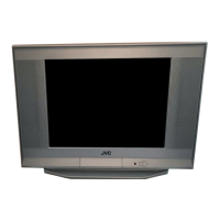
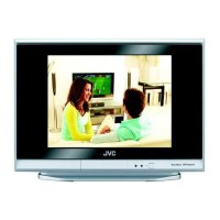
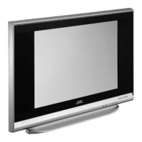
JVC AV-21MT16/Z Specifications

General IconGeneral
Screen Size21 inches
Display TechnologyCRT
Aspect Ratio4:3
Remote ControlYes
TunerAnalog
Input PortsComposite

Summary

SECTION 1 PRECAUTION

1.1 SAFETY PRECAUTIONS

General safety precautions for servicing, emphasizing original design and replacement parts.

Isolation Check (Safety for Electrical Shock Hazard)

Procedure for performing isolation and leakage current checks to ensure electrical shock safety.

SECTION 2 SPECIFIC SERVICE INSTRUCTIONS

2.1 FEATURES

Highlights new chassis design, flat CRT, wide voltage input, input terminals, I2C bus, AUTO PROGRAM, ECO MODE.

2.3 MAIN CPU [MAIN PWB : IC701] PIN FUNCTION

Detailed pin functions for the main CPU IC701 on the MAIN PWB, essential for service.

SECTION 3 DISASSEMBLY

3.1 DISASSEMBLY PROCEDURE [AV-21MT16/Z, AV-21MT36/Z]

Step-by-step guide for disassembling the TWIN PORT BASS BLASTER UNIT and REAR COVER.

3.3 DISASSEMBLY PROCEDURE [AV-29MT16/Z, AV-29MT36/Z]

Disassembly steps for the CHASSIS, AV TERMINAL BOARD, CONTROL BASE, and SPEAKER on larger models.

3.4 REPLACEMENT OF MEMORY IC

Procedure for replacing the memory IC (IC702), including setting SYSTEM CONSTANT.

SECTION 4 ADJUSTMENT

4.4 ADJUSTMENT ITEMS

Lists all adjustable items, categorized into B1 VOLTAGE, IF CIRCUIT, VIDEO CIRCUIT, DEFLECTION CIRCUIT, etc.

4.7 ADJUSTMENT PROCEDURE

Detailed procedures for specific adjustments like B1 VOLTAGE, FOCUS, IF CIRCUIT, and VIDEO CIRCUIT.

4.7.4 VIDEO CIRCUIT ADJUSTMENTS

Table of initial setting values for SCREEN, CUTOFF, WDR, BRIGHT, CONT, COLOUR, TINT, SHARP, Y DELAY.

SECTION 5 TROUBLESHOOTING

5.1 SELF CHECK FUNCTIONS

Overview of self-check functions, abnormalities detection, and failure indication via POWER LED.

5.1.2 SELF CHECK ITEMS

Details detection methods and states of abnormality for B1 over-current and CRT neck protection.

Related product manuals