1-14 (No.MB191)
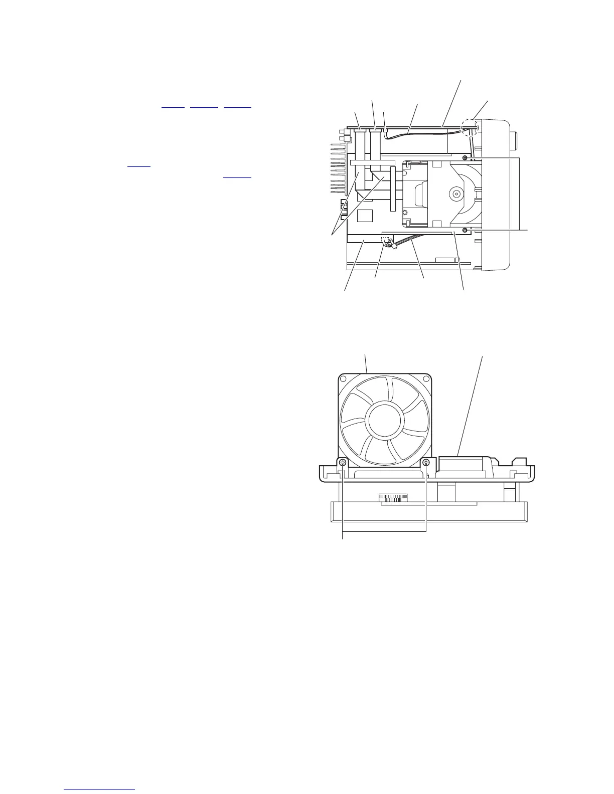
3.1.8 Removing the center chassis assembly
(See Fig.16)
• Prior to performing the following procedures, remove the metal
cover, tuner, video board and rear panel.
(1) From the top side of the main body, disconnect the card
wires from the connectors (CN11
, CN511, CN513) on the
main body.
Reference:
When reassembly, pass the card wire through the sec-
tion f of the main board before connecting the card wire
to the connector CN11
.
(2) Disconnect the wire from the connector CN105 on the
speaker terminal board.
(3) Remove the two screws P attaching the center chassis as-
sembly.
(4) Take out the center chassis assembly from the main body.
Fig.16
3.1.9 Removing the fan
(See Fig.17)
• Prior to performing the following procedure, remove the metal
cover, tuner, video board, rear panel and center chassis as-
sembly.
From the bottom side of the center chassis assembly, remove
the two screws Q attaching the fan.
Fig.17
Main board
CN513
Speaker terminal board
CN11
CN105
CN511
Card wire
Card
wires
P
Center chassis assembly
Wire
f
Center chassis assembly
Q
Fan
 Loading...