Masterpage:Right+
EN 11
Filename [DR-MH30EU_04Name.fm]
INDEX
Page 11 Friday, 11 June 2004 21:18
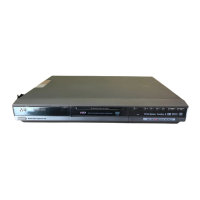
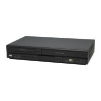
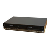
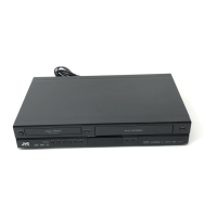
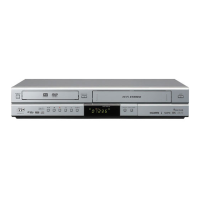
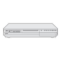
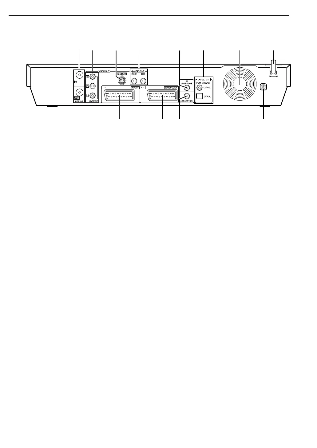
Rear View
A Antenna Connectors (ANTENNA IN/OUT) 墌 pg. 17
B Component Video Output Connectors (COMPONENT
VIDEO OUT) 墌 pg. 17
C S-video Output Connector (S-VIDEO OUT)
墌 pg. 17, 60
D Audio Output Connectors (AUDIO OUT (RIGHT/LEFT))
墌 pg. 60
E AV COMPU LINK Connector*
* Not function with this unit.
F Digital Audio Output Connectors
(DIGITAL OUT (COAXIAL/OPTICAL))
墌 pg. 62, 66
G Cooling Fan
● This prevents the temperature from rising inside the unit.
Do not remove it.
● Install the unit so as not to block the area around the fan.
● The cooling fan on the rear of the unit may be activated even if
the unit is turned off in the following cases;
— In the Automatic Satellite Programme Recording standby
mode (墌 pg. 48), slightly before the starting time of VPS/PDC
recording (墌 pg. 45)
— If you connect the decoder or the satellite receiver to L-2 IN/
DECODER and if “L-2 SELECT” is set to “DECODER” or “SAT
VIDEO” or “SAT S-VIDEO”. (墌 pg. 61)
— when “JUST CLOCK” is set to “ON” (墌 pg. 73)
(Set “JUST CLOCK” to “OFF” if you mind the noise of the fan.)
H Mains Power Cord 墌 pg. 17
I L-1 Input/Output Connector (L-1 IN/OUT)
墌 pg. 17, 60,
61, 65, 66
J L-2 Input/Decoder Connector
(L-2 IN/DECODER)
墌 pg. 23, 60, 65, 66
K Satellite Control Connector (SAT CONTROL)
墌 pg. 23
L Region Number Label
墌 pg. 6
AEFCDBGH
JK LI
DR-MH30EU_00.book Page 11 Monday, June 14, 2004 8:03 AM
 Loading...