1-22 (No.MB531)
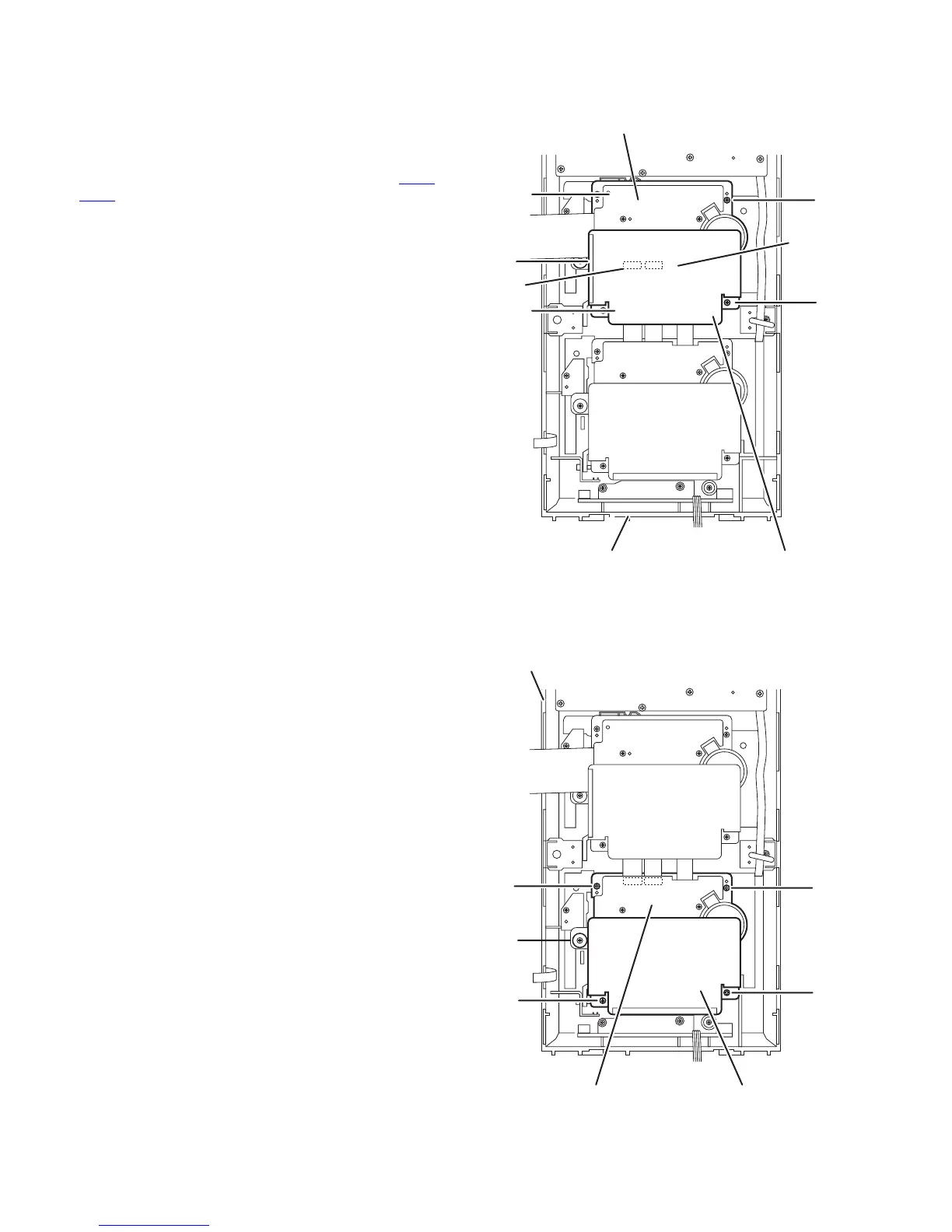
3.1.16 Removing the cassette A mechanism assembly
(See Fig.23)
• Remove the metal cover and front panel assembly.
(1) From the inside of the front panel assembly, remove the
four screws V and W attaching the cassette A mechanism
assembly.
(2) Disconnect the card wires from the connectors (CN46
,
CN47) on the cassette A mechanism assembly.
(3) Take out the cassette A mechanism assembly from the
front panel assembly.
Reference:
Remove the trans shield as required.
Fig.23
3.1.17 Removing the cassette B mechanism assembly
(See Fig.24)
• Remove the metal cover and front panel assembly.
(1) From the inside of the front panel assembly, remove the
four screws V and screw W attaching the cassette B mech-
anism assembly.
(2) Take out the cassette B mechanism assembly from the
front panel assembly.
Reference:
Remove the trans shield as required.
Fig.24
Cassette A mechanism assembly
Front panel assembly Trans shield
V
CN47
CN46
V
V
V
W
Cassette B mechanism assembly
Front panel assembly
Trans shield
W
VV
V
V
 Loading...