FS-SD550R/FS-SD770R/FS-SD990R
1-10
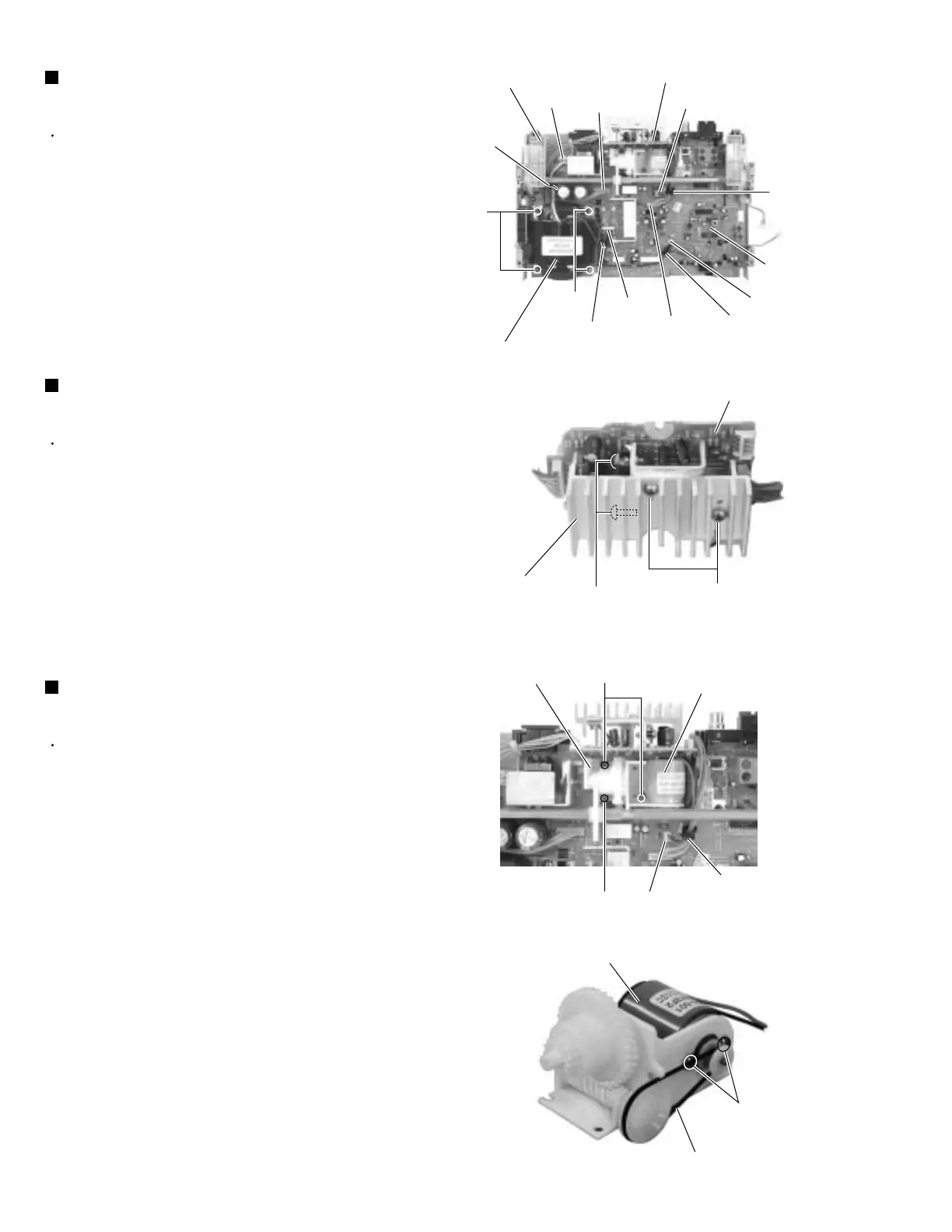
Prior to performing the following procedure, remove
the CD mechanism base assembly.
Disconnect the wires from connector CN102 and
CN193 on the main board and release them from the
cord stopper respectively.
Remove the two screws K and the two screws L
attaching the heat sink and the power amplifier
board.
1.
2.
Removing the power amplifier board
(See Fig.21 and 22)
Prior to performing the following procedure, remove
the CD mechanism base assembly.
Disconnect the wires from connector CN191 and
CN192 on the main board and release them from the
cord stopper respectively.
Remove the four screws M attaching the transformer
assembly.
1.
2.
Removing the transformer assembly
(See Fig.21)
Prior to performing the following procedure, remove
the CD mechanism base assembly and the door arm
assembly.
Disconnect the wires from connector CN106 on the
main board and release it from the cord stopper.
Remove the three screws N attaching the gear
motor assembly. Remove the gear motor assembly
with the gear motor stopper.
Remove the belt from the gear motor assembly.
Remove the two screws O from the gear motor
assembly.
1.
2.
3.
4.
Removing the gear motor assembly
(See Fig.23 and 24)
Fig.21
Fig.22
Fig.23
Fig.24
Power amplifier board
Door arm assembly
CN191
CN193
Cord stopper
Cord
stopper
Main board
CN106
CN181
CN192
CN102
Cord stopper
M
M
Transformer assembly
Power amplifier board
Heat sink
K
L
Gear motor stopper
Gear motor assembly
Cord stopper
CN106
N
N
Motor
Belt
O
Cord stopper