1-11
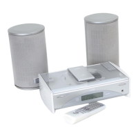
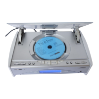
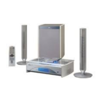
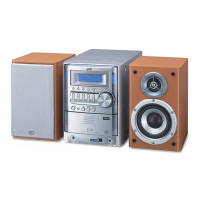
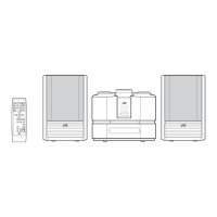
FS-SD5/FS-SD7/FS-SD9
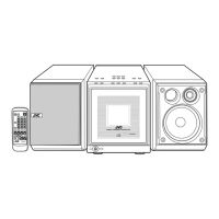
Prior to performing the following procedure, remove
the CD mechanism base assembly.
Disconnect the harness from connector CN181 on
the main board.
Remove the two screws P on the left side of the
body. Move the fan motor assembly upward to
remove it from the base chassis.
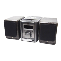
Remove the two screws Q and the fan motor from
the fan bracket.
1.
2.
3.
Removing the fan motor assembly
(See Fig.24 and 25)
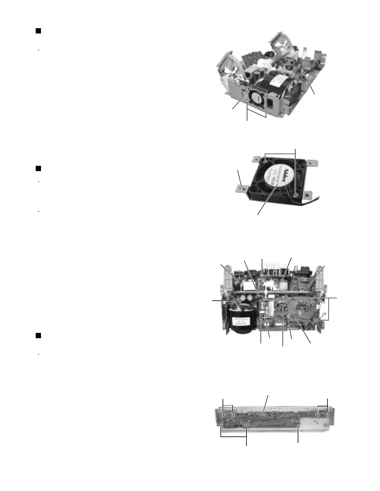
Prior to performing the following procedure, remove
the front panel assembly.
Remove the seven screws S attaching the front
panel board inside the front panel assembly.
1.
Removing the front panel board
(See Fig.27)
<Front panel assembly>
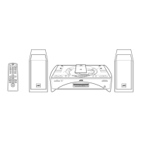
Prior to performing the following procedure, remove
the CD mechanism base assembly and the door arm
assembly.
To facilitate operation process, remove the gear
motor assembly before performing the following
procedure.
Disconnect the harnesses from connector CN102,
CN106, CN191, CN192, CN193 and CN181 on the
main board.
Remove the five screws R attaching the main board
with the cord clamp.
1.
2.
Removing the main board (See Fig.26)
Fig.24
Fig.25
Fig.26
Fig.27
Main bard
CN181
Fan motor
P
Fan motor
Fan bracket
Q
Gear motor assembly
Main board
CN193
CN191
CN106
CN181
CN102
CN192
R
R
R
R
Front panel assembly
S
S
S
S
 Loading...