EasyManua.ls Logo

JVC FS-SD5R Service Manual

JVC FS-SD5R
62 pages
To Next Page IconTo Next Page
Page #1 background imageLoading...
Page #1 background image
FS-SD5R/FS-SD7R/FS-SD9R
SERVICE
MANUAL
FS-SD5R
FS-SD7R
/
FS-SD9R
Area
Suffix
FS-SD5R/FS-SD7R
U.K.
E
---
Continental
Europe
EN
----
Northern
Europe
E
---
Continental
Europe
EN
----
Northern
Europe
Eastern
Europe
EE
--
Russian
Federation
Hong
Kong
DIGITAL
AUDIO
2)
@BRDS
These
models
are
different
only
speaker
systems.
FS-SD7R
and
FS-SD9R
are
different
only
speaker
cabinet.
FS-SD7R,
FS-SD9R
Contents
These
models
not
have
adjustment.
Safety
Precautions
--------------------+--
1-2
Flow
of
functional
operation
Preventing
static
electricity
-------------
1-3
until
TOC
read
------------
2-10
Important
for
laser
products
------------
1-4
Description
of
major
ICs
-----------------
2-11
InstruCtionS
-------------------2----er0-0
7
1-5~11
Block
diagram
------------------------------
2-26
Disassembly
method
---------------------
2-1
Standard
schematic
diagrams
---------
2-27
Maintenance
of
laser
pickup
-----------
2-9
Printed
circuit
boards
---------------------
2-32~34
Paris
WiSk
etre
ssestiestesasen
e
aov
arenes
3-1~15
This
service
manual
is
made
from
100%
recycled
paper.
COPYRIGHT
©
2000
VICTOR
COMPANY
OF
JAPAN,
LTD.
No.20829
Apr.
2000

Other manuals for JVC FS-SD5R

Question and Answer IconNeed help?

Do you have a question about the JVC FS-SD5R and is the answer not in the manual?

JVC FS-SD5R Specifications

General IconGeneral
BrandJVC
ModelFS-SD5R
CategorySpeaker System
LanguageEnglish

Summary

Safety Precautions

Warnings and Cautions

General safety warnings and cautions for product operation and service.

Preventing Static Electricity

Grounding Procedures

Steps for grounding to prevent static discharge damage to components.

Handling Optical Pickup

Guidelines for safely handling the optical pickup unit.

Laser Product Safety Information

Instructions and General Safety

General Safety Instructions

Do's and don'ts for safe operation and maintenance of the equipment.

Product Introduction and Features

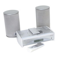
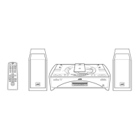
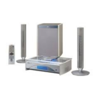
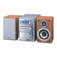
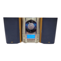
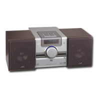
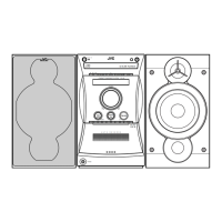
Overview of the system's capabilities and key features.

Getting Started

System Accessories

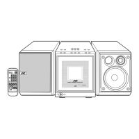
List of items included with the JVC system.

Remote Control Setup

Instructions for inserting batteries and using the remote control.

Connecting Antennas

Guide for connecting FM and AM antennas to the system.

Basic Operations

Speaker and External Connections

Steps for connecting speakers, subwoofers, and external audio devices.

Power and Display Adjustments

How to turn the system on/off and adjust display brightness.

Volume and Audio Controls

Adjusting volume, tone, and muting functions.

Using the Tuner

Tuner Operation Modes

Using the tuner for manual, auto, and preset station tuning.

Station Tuning Methods

Details on tuning in stations using various methods.

Presetting and RDS Features

How to preset stations and utilize RDS functions.

Using the CD Player

FM Reception Modes

Changing FM reception modes for better signal quality.

CD Playback Basics

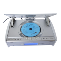
Inserting, unloading, and playing CDs.

Advanced CD Playback

Programming, random, and repeat playback functions.

Using External Equipments

Modifying CD Programs

How to edit programmed track sequences.

Listening and Recording

Connecting and using external audio sources and recording.

Using the Timers

Clock and Daily Timer Setup

Setting the system clock and daily timer for automated operation.

Sleep Timer Function

Setting the sleep timer to automatically turn off the system.

Care and Maintenance

CD Handling and Cleaning

Proper handling and cleaning procedures for compact discs.

Moisture Condensation

How to handle moisture condensation inside the system.

Troubleshooting

Specifications

Disassembly Method

Main Body Disassembly

Step-by-step guide to disassembling the main unit.

CD Mechanism Base Assembly Removal

Procedure for removing the CD mechanism base assembly.

Door Arm Assembly Removal

Steps to remove the door arm assembly.

Power Amplifier Board Removal

Procedure for removing the power amplifier board.

Transformer Assembly Removal

Steps to remove the transformer assembly.

Gear Motor Assembly Removal

Procedure for removing the gear motor assembly.

Fan Motor Assembly Removal

Steps to remove the fan motor assembly.

Main Board Removal

Procedure for removing the main board.

Front Panel Board Removal

Steps to remove the front panel board.

Speaker Terminal Board Removal

Procedure for removing the speaker terminal board.

CD Mechanism Board Removal

Steps to remove the CD mechanism board and assembly.

Jack Board Removal

Procedure for removing the jack board.

Switch Board Removal

Steps to remove the switch board.

LED Board Removal

Procedure for removing the LED board.

Laser Pickup Maintenance

Cleaning the Pickup Lens

Instructions for cleaning the laser pickup lens.

Laser Diode Life and Symptoms

Information on laser diode lifespan and associated symptoms.

Laser Pickup Replacement

Functional Operation Flow (TOC Read)

Description of Major ICs

LA4905 (IC301): 2ch BTL Power IC

Pin layout and block diagram for the power IC.

AN8806SB-W (IC601): RF & Servo Amp.

Pin layout and block diagram for the RF/Servo amplifier IC.

AN8806SB-W (IC601) Pin Function

Detailed pin functions for the RF/Servo amplifier IC.

MN35510 (IC603): Digital Servo & Signal Processor

Terminal layout and block diagram for the digital servo IC.

MN35510 (IC603) Description

Detailed description of the digital servo IC's functions.

UPD780024AGKA11 (IC701): CPU

Pin layout and block diagram for the CPU.

UPD780024AGKA11 (IC701) Pin Function

Detailed pin functions for the CPU.

BA15218F-XE (IC102): Dual Op. Amp.

Pin layout and block diagram for the dual op-amp.

KIA78S06P-T (IC702): Regulator

Pin layout and block diagram for the regulator IC.

NJM4580D-D (IC101): Dual Op. Amp.

Pin layout and block diagram for the dual op-amp.

LA6541-X (IC602): Servo Driver

Pin layout, block diagram, and pin functions for the servo driver.

LC72136N (IC2): PLL Frequency Synthesizer

Pin layout, block diagram, and pin functions for the PLL synthesizer.

TA2057N (IC1): FM/AM IF AMP & Detector

Block diagrams and pin functions for the FM/AM IF AMP.

TA8409F-W (IC108): Bridge Driver

Pin layout, pin function, and block diagram for the bridge driver.

UPD78L5J-T (IC191): Regulator

Pin layout and block diagram for the regulator IC.

BD3861FS-X (IC501): Audio Sound Control

Pin layout, block diagram, and pin functions for audio control IC.

BU1923 (IC4): RDS Detector

Terminal layout, pin function, and block diagram for RDS detector.

Block Diagram

Standard Schematic Diagrams

CD Servo Control Section

Schematic diagram for the CD servo control circuit.

Power Supply & Main Circuit Section

Schematic for power supply and main functional circuits.

System Control Section

Schematic diagram for the system control circuits.

Tuner Section (B/E/EN/EV/UB Version)

Schematic for the tuner section for specific regional versions.

Tuner Section (EE Version)

Schematic for the tuner section for the EE version.

Printed Circuit Boards

Line Board (Forward Side)

Layout of the line board's component side.

CD Servo Board (Forward Side)

Layout of the CD servo board's component side.

Line Board (Reverse Side)

Layout of the line board's solder side.

CD Servo Board (Reverse Side)

Layout of the CD servo board's solder side.

Parts List

Contents of Parts List

Overview of the parts list sections: exploded views, electrical, packing.

General Assembly Parts List

List of mechanical parts for general assembly.

Exploded View of General Assembly

Illustrated exploded view of the system's mechanical parts.

General Assembly Parts List (Continued)

Additional mechanical parts for general assembly.

Electrical Parts List (Main Board)

List of electrical components for the main board.

Electrical Parts List (CD Board)

List of electrical components for the CD board.

Packing Materials and Accessories Parts List

Packing Parts List Details

Detailed list of packing materials and their quantities.

Accessories List Details

Detailed list of system accessories and their quantities.

Related product manuals