1-7
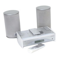
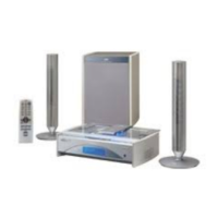
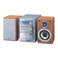
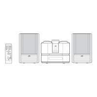
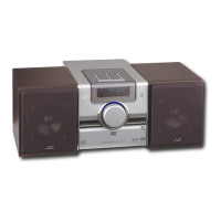
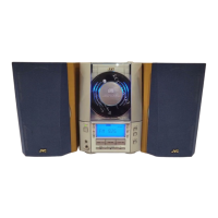
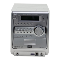
FS-SD5/FS-SD7/FS-SD9
Prior to performing the following procedure, remove
the rear cover, the side covers and the front panel
assembly.
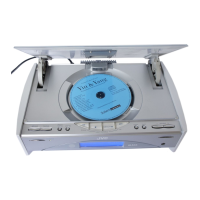
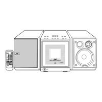
Remove the four screws E attaching the CD door on
the upper side of the body.
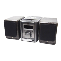
Disconnect the card wire from connector CN104 and
CN105 of the main board in the front part of the
body. Disconnect the card wire from CN101 of the
main board on the right side, and the harness from
CN705 and CN708 of the CD mechanism base
assembly respectively.
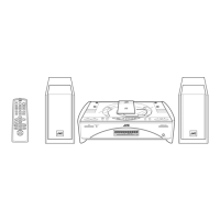
Remove the four screws F attaching the CD
mechanism base assembly on the upper side of the
body. Remove the screw I attaching the earth
terminal on the right side.
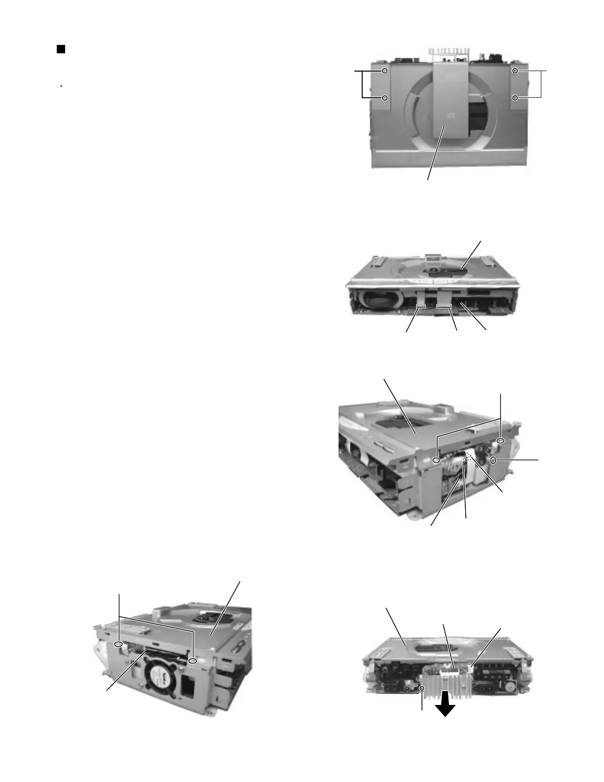
Remove the screw G attaching the heat sink board
on the back of the body. Disconnect the harness
from connector CN301 and pull the heat sink board
fully outward.
1.
2.
3.
4.
Removing the CD mechanism base
assembly (See Fig.6 to 13)
Fig.6
Fig.7
Fig.8
Fig.9
Fig.10
E
E
CD door
CD mechanism base assembly
Main bard
CN105
CN104
F
I
CD mechanism base assembly
Main bard
CN101
CN708
CN705
F
CD mechanism base assembly
CN804
CD mechanism base assembly
CN301
G
Heat sink board
 Loading...