39
erty
i
WQER
T
w
o
p
u
U
Y
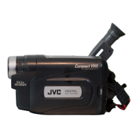
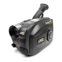
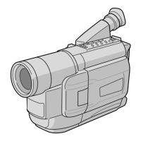
Connectors
w J terminal (JLIP (Joint Level Interface Protocol)
Connector.)
(Located beneath the jack cover)
• Connect the Editing Cable when performing
Random Assemble Editing (
Z pg. 32).
•It is used to connect the camcorder to a device
such as a personal computer.
For further detail consult your nearest JVC
dealer.
Information (in English) is also availble at our
home page: http://www.jvc-victor.co.jp/
e DC IN Jack ......................................... Z pg. 7
The jacks r to y are located beneath the jack
cover.
r VIDEO OUT Jack ............................... Z pg. 27
t RF DC OUT Jack................................ Z pg. 27
y AUDIO OUT Jack .............................. Z pg. 27
Indicators
u Tally Lamp ......................................... Z pg. 12
i Power On Indicator ........................... Z pg. 12
Other Parts
o Camera sensor
Be careful not to cover this area; built-in here is
the sensor necessary for shooting.
p Microphone
Q Shoulder Strap Eyelets ........................ Z pg. 11
W Clock Battery Compartment ................ Z pg. 8
E Battery Pack Mount ........................... Z pg. 6
R Electronic Viewfinder......................... Z pg. 8
T LENS COVER Switch ......................... Z pg. 12
Y Grip Strap .......................................... Z pg. 11
U Tripod Mounting Socket ...................... Z pg. 11
Downloaded from: https://www.usersmanualguide.com/
 Loading...