GETTING STARTED
GETTING STARTED
EN 7
MasterPage: Start_Right
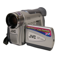
Controls
A Index Button [INDEX] (墌 pg. 23)
Navigation Button [INDEX] (墌 pg. 36)
B Thumbnail Storing Button [STORE] (墌 pg. 36)
C D.S.C. Playback Select Button [SELECT]
(墌 pg. 22, 23)
D VIDEO/MEMORY Switch (墌 pg. 12)
E Stop Button [8] (墌 pg. 17)
Backlight Compensation Button [BACK LIGHT]
(墌 pg. 33)
F Rewind Button [
3
] (墌 pg. 17)
Manual Focus Button [FOCUS] (墌 pg. 32)
G Play/Pause Button [4/9] (墌 pg. 17)
Exposure Button [EXPOSURE] (墌 pg. 33)
H Fast-Forward Button [
5
] (墌 pg. 17)
Night Button [NIGHT] (墌 pg. 32)
I E-Mail Clip Recording Button [E-MAIL] (墌 pg. 24)
Information Button [INFO] (墌 pg. 23)
J Up Button [ ] (墌 pg. 27)
LCD Monitor Brightness Control [BRIGHT ]
(墌 pg. 13)
K LED Light Button [LIGHT] (墌 pg. 31)
L Set Button [SET] (墌 pg. 27)
M Down Button [ ] (墌 pg. 27)
LCD Monitor Brightness Control [BRIGHT ]
(墌 pg. 13)
N Menu Button [MENU] (墌 pg. 27)
O Snapshot Button [SNAPSHOT] (墌 pg. 21, 32)
P Power Zoom Lever [T/W] (墌 pg. 16)
Speaker Volume Control [VOL. +, –] (墌 pg. 17)
Q Dioptre Adjustment Control (墌 pg. 13)
R Recording Start/Stop Button (墌 pg. 15)
S Lock Button (墌 pg. 12)
T Power Switch [A, M, PLAY, OFF] (墌 pg. 12)
U Cassette Open/Eject Switch [OPEN/EJECT]
(墌 pg. 14)
V Battery Release Switch [BATT.] (墌 pg. 11)
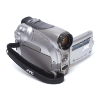
Connectors
The connectors are located beneath the covers.
W USB (Universal Serial Bus) Connector (墌 pg. 39)
X Digital Video Connector [DV IN*/OUT] (i.Link**)
(墌 pg. 38, 39)
Y DC Input Connector [DC] (墌 pg. 11)
Z Microphone connector [MIC] (墌 pg. 29, 40)
(An optional microphone can be used during video
recording and audio dubbing. To stabilise the
microphone, use of an optional shoe adapter is
recommended.)
a S-Video/Audio/Video Input*/Output Connector [S/AV]
(墌 pg. 18, 37, 42)
* GR-D231/230 only
**i.Link refers to the IEEE1394-1995 industry specification
and extensions thereof. The logo is used for products
compliant with the i.Link standard.
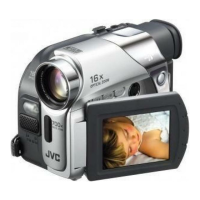
Indicators
b POWER/CHARGE Lamp (墌 pg. 11, 15)
c Tally Lamp (墌 pg. 15, 29)
Other Parts
d Monitor Latch (墌 pg. 15)
e LCD Monitor (墌 pg. 15, 16)
f Viewfinder (墌 pg. 13)
g Shoulder Strap Eyelet (墌 pg. 10)
h Battery Pack Mount (墌 pg. 11)
i Speaker (墌 pg. 17)
j Grip Strap (墌 pg. 13)
k Lens
l LED Light (墌 pg. 31)
(When using an optional conversion lens, it may cover
this area and block the light.)
m Stereo Microphone (墌 pg. 40)
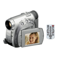
n Remote Sensor (墌 pg. 19)
o Camera Sensor
(Be careful not to cover this area, a sensor necessary
for shooting is built-in here.)
p Stud Hole (墌 pg. 13)
q Tripod Mounting Socket (墌 pg. 13)
r Cassette Holder Cover (墌 pg. 14)
s Card Cover [MEMORY CARD] (墌 pg. 14)
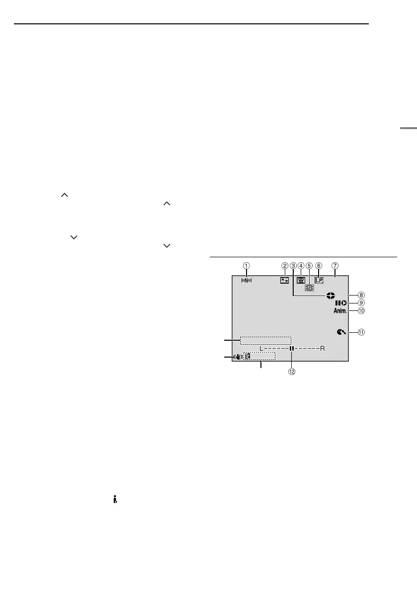
LCD Monitor/Viewfinder Indications
During Video Recording Only
a Navigation Indicator (墌 pg. 35)
B Selected Wipe/Fader Effect Indicator (墌 pg. 34)
C Tape Running Indicator (墌 pg. 15)
(Rotates while tape is running.)
D Selected Wide Mode Indicator (墌 pg. 28)
E Thumbnail Storing Indicator (墌 pg. 35)
F Recording Speed Mode (SP/LP) (墌 pg. 27)
G Tape Remaining Time (墌 pg. 15)
H REC: (Appears during recording.) (墌 pg. 15)
PAUSE: (Appears during Record-Standby mode.)
(墌 pg. 15)
I Insert Editing/Insert Editing Pause Mode (墌 pg. 40)
J 5S/Anim.: Displays the 5-Second Recording mode or
Animation recording mode. (墌 pg. 28)
K Wind Cut Indicator (墌 pg. 29)
L Auxiliary Microphone Level Indicator
(Appears when an optional microphone is connected.
墌 pg. 29, “AUX MIC” )
M Time Code (墌 pg. 29, 31)
N Digital Image Stabiliser (“DIS”) (墌 pg. 28)
O Sound Mode Indicator (墌 pg. 27)
(Appears for approx. 5 seconds after turning on the
camcorder.)
SOUND
12
BIT
1h40m
t
r
e
15:55
REC
GR-D231PAL.book Page 7 Thursday, January 22, 2004 2:57 PM