SERVICE MANUAL
COPYRIGHT © 2003 VICTOR COMPANY OF JAPAN, LTD.
No.86722
2003/04
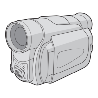
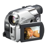
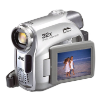
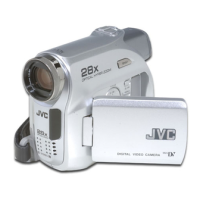
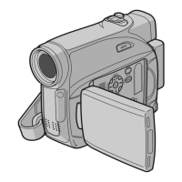
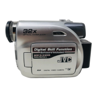
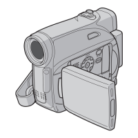
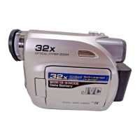
DIGITAL VIDEO CAMERA
86722200304
GR-D30UB,GR-D30US,GR-D31US,
GR-D70US,GR-D90UB,GR-D90US,GR-D91US
SPECIFICATION (The specifications shown pertain specifically to the model GR-D30US, GR-D70US, GR-D90US)
Camcorder
General
Digital Video Camera
Digital Still Camera Function
Connectors
AC Adapter
For disassembling and assembling of MECHANISM ASSEMBLY, refer to the SERVICE MANUAL No.86700 (MECHANISM ASSEMBLY).
Power supply : DC 11.0 V (Using AC Adapter)
DC 7.2 V (Using battery pack)
Power consumption
LCD monitor off,
viewfinder on : Approx. 3.4 W
LCD monitor on,
viewfinder off : Approx. 4.7 W
Dimensions
(W x H x D) : 76 mm x 94 mm x 143 mm
(3" x 3-3/4" x 5-11/16") (GR-D90)
69 mm x 94 mm x 143 mm
(2-3/4" x 3-3/4" x 5-11/16") (GR-D70/D30)
(with the LCD monitor closed and the viewfinder
pushed back in)
Weight : Approx. 550 g (1.3 lbs) (GR-D90)
Approx. 525 g (1.2 lbs) (GR-D70/D30)
Operating temperature : 0°C to 40°C (32°F to 104°F)
Operating humidity : 35% to 80%
Storage temperature : -20°C to 50°C (-4°F to 122°F)
Pickup : 1/6" CCD
Lens : F 1.6, f = 2.7 mm to 43.2 mm, 16:1 power zoom lens
Filter diameter : Ø37 mm
LCD monitor : 3.5" diagonally measured, LCD panel/TFT active
matrix system (GR-D90)
2.5" diagonally measured, LCD panel/TFT active
matrix system (GR-D70/D30)
Viewfinder : Electronic viewfinder with 0.24" black/white LCD
Speaker : Monaural
Format : DV format (SD mode)
Signal format : NTSC standard
Recording/Playback format : Video: Digital component recording
: Audio: PCM digital recording,
32 kHz 4-channel (12-bit),
48 kHz 2-channel (16-bit)
Cassette : Mini DV cassette
Tape speed : SP : 18.8 mm/s
LP : 12.5 mm/s
Maximum recording time : SP : 80 min.
(using 80 min. cassette) LP : 120 min.
Storage media : SD Memory Card/MultiMediaCard
Compression system : JPEG (compatible)
File size : 2 modes (1024 x 768 pixels, 640 x 480 pixels)
Picture quality : 2 modes (FINE/STANDARD)
Approximate number of
storable images : pg. 18.
S-Video
Output : Y : 1 V (p-p), 75 Ω, analog
C : 0.29 V (p-p), 75 Ω, analog
Input* : Y : 0.8 V (p-p) -1.2 V (p-p), 75 Ω, analog
C : 0.2 V (p-p) -0.4 V (p-p), 75 Ω, analog
AV
Video output : 1 V (p-p), 75 Ω, analog
Video input* : 0.8 V (p-p) -1.2 V (p-p), 75 Ω, analog
Audio output : 300 mV (rms), 1 kΩ, analog, stereo
Audio input* : 300 mV (rms), 50 kΩ, analog, stereo
DV
Output : 4-pin, IEEE 1394 compliant
Input : 4-pin, IEEE 1394 compliant
USB* :5-pin
* GR-D90/D70 only
Power requirement
U.S.A and Canada : AC 120 V ~, 60 Hz
Other countries : AC 110 V to 240 V ~, 50 Hz/60 Hz
Output : DC 11 V , 1 A
Specifications shown are for SP mode unless otherwise indicated. E & O.E. Design and specifications subject
to change without notice.
GR-D30UB,GR-D30US,GR-D31US,GR-D70US,GR-D90UB,GR-D90US,GR-D91US M3D123,M3D143,M3D127,M3D147