EasyManua.ls Logo

JVC GR-D70EK

JVC GR-D70EK
24 pages
To Next Page IconTo Next Page
Loading...
SERVICE MANUAL
COPYRIGHT © 2003 VICTOR COMPANY OF JAPAN, LTD.
No.86733
2003/04
DIGITAL VIDEO CAMERA
86733200304
GR-D70EK,GR-D70EX,
GR-D70E
Y,GR-D70EZ
SPECIFICATION
Camcorder
General
Digital Video Camera
Digital Still Camera Function
Connectors
AC Adapter
For disassembling and assembling of MECHANISM ASSEMBLY, refer to the SERVICE MANUAL No.86700 (MECHANISM ASSEMBLY).
PAL
Power supply : DC 11.0 V (Using AC Adapter)
DC 7.2 V (Using battery pack)
Power consumption
LCD monitor off,
viewfinder on : Approx. 3.4 W
LCD monitor on,
viewfinder off : Approx. 4.7 W
Dimensions
(W x H x D) : 69 mm x 94 mm x 143 mm
(with the LCD monitor closed and the viewfinder
pushed back in)
Weight : Approx. 525 g
Operating temperature : 0°C to 40°C
Operating humidity : 35% to 80%
Storage temperature : -20°C to 50°C
Pickup : 1/6" CCD
Lens : F 1.6, f = 2.7 mm to 43.2 mm, 16:1 power zoom lens
Filter diameter : Ø37 mm
LCD monitor : 2.5" diagonally measured, LCD panel/TFT active
matrix system
Viewfinder : Electronic viewfinder with 0.24" black/white LCD
Speaker : Monaural
Format : DV format (SD mode)
Signal format : PAL standard
Recording/Playback format : Video: Digital component recording
: Audio: PCM digital recording,
32 kHz 4-channel (12-bit),
48 kHz 2-channel (16-bit)
Cassette : Mini DV cassette
Tape speed : SP : 18.8 mm/s
LP : 12.5 mm/s
Maximum recording time : SP : 80 min.
(using 80 min. cassette) LP : 120 min.
Storage media : SD Memory Card/MultiMediaCard
Compression system : JPEG (compatible)
File size : 2 modes (1024 x 768 pixels, 640 x 480 pixels)
Picture quality : 2 modes (FINE/STANDARD)
Approximate number of
storable images : pg. 18.
S-Video
Output : Y : 1 V (p-p), 75 , analogue
C : 0.29 V (p-p), 75 , analogue
Input* : Y : 0.8 V (p-p) -1.2 V (p-p), 75 , analogue
C : 0.2 V (p-p) -0.4 V (p-p), 75 , analogue
AV
Video output : 1 V (p-p), 75 , analogue
Video input* : 0.8 V (p-p) -1.2 V (p-p), 75 , analogue
Audio output : 300 mV (rms), 1 k, analogue, stereo
Audio input* : 300 mV (rms), 50 k, analogue, stereo
DV
Output : 4-pin, IEEE 1394 compliant
Input : 4-pin, IEEE 1394 compliant
USB* :5-pin
EDIT : Ø3.5 mm, 2-pole
* GR-D70 only
Power requirement : AC 110 V to 240 V ~, 50 Hz/60 Hz
Output : DC 11 V , 1 A
Specifications shown are for SP mode unless otherwise indicated. E & O.E. Design and specifications subject
to change without notice.
GR-D70EK,GR-D70EX,GR-D70EY,GR-D70EZ M3D127

Other manuals for JVC GR-D70EK

Question and Answer IconNeed help?

Do you have a question about the JVC GR-D70EK and is the answer not in the manual?

JVC GR-D70EK Specifications

General IconGeneral
TypeMiniDV
Optical Zoom16x
Digital Zoom700x
LCD Screen Size2.5 inches
Optical Sensor Size1/4 inch
Image StabilizerElectronic
SensorCCD
ViewfinderColor
Still Image Resolution640 x 480 pixels
Recording MediaMiniDV
Video FormatDV
Zoom16x optical, 700x digital
InterfaceIEEE 1394 (FireWire), USB
Weight480g (with battery)

Summary

SPECIFICATION

General Device Specifications

Covers power supply, consumption, dimensions, weight, and operating conditions for the device.

Camcorder Operational Specs

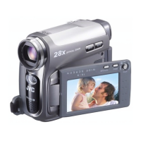
Details pickup system, lens, LCD monitor, viewfinder, speaker, and DV format specifications.

Digital Still Camera Features

Outlines storage media, compression system, file size, and picture quality for still images.

Connectors and Power Requirements

Lists various input/output connectors and AC adapter power requirements.

PRECAUTIONS

Servicing Safety Precautions

Covers handling, part replacement, hazard warnings, and specific cautionary notices during service.

Post-Servicing Safety Checks

Details procedures for insulation resistance, dielectric strength, and leakage current tests.

SPECIFIC SERVICE INSTRUCTIONS

Assembly and Disassembly Preparation

General guidelines, tools, and torque specifications for device disassembly procedures.

Cabinet Parts Disassembly Guide

Step-by-step guide for disassembling the device's outer casing and cabinet components.

Camera Section Board Disassembly

Procedures for accessing internal camera components and board assemblies.

Viewfinder (VF) Assembly Disassembly

Detailed steps for taking apart the viewfinder unit, including FPC handling.

Monitor Assembly Disassembly Steps

Instructions for disassembling the LCD monitor assembly, covering both 2.5" and 3.5" models.

OP Block and CCD Board Disassembly

Steps for disassembling the OP block assembly and CCD board, including component replacement.

Service Notes and Screw Management

Notes on screw management, tightening torque, and using jig connector cables.

Cassette Tape Ejection Procedure

Method for ejecting a cassette tape when electrical failure prevents normal operation.

Emergency Display Error Codes

Explanation of error codes displayed on the unit and their possible causes.

ADJUSTMENT PROCEDURES

Adjustment Preparation and Equipment

General advice on preparation and a list of required test equipment for adjustments.

Required Servicing Tools List

List and description of specialized tools required for camera system adjustments.

Jig Connector Cable Usage Guide

Details on connecting test equipment using a jig connector cable and its schematic.

Mechanism Compatibility Tape Test

Procedures for checking tape patterns and adjusting guide rollers for compatibility.

Electrical Adjustment with PC

Steps for performing electrical adjustments using a personal computer and service support system.

Related product manuals