TABLE OF CONTENTS
Section Title Page Section Title Page
Important Safety Precautions
INSTRUCTIONS
1. DISASSEMBLY
1.1 Manually removing the cassette tape ......................... 1-1
1.2 Removing the major parts ........................................... 1-2
1.2.1 How to read the procedure table........................... 1-2
1.2.2 Disassembly procedure ........................................ 1-2
1.3 Emergency display function ........................................ 1-4
1.3.1 Displaying the EMG information ........................... 1-4
1.3.2 Clearing the EMG history ...................................... 1-4
1.3.3
Details of the OSD display in the EMG display mode
... 1-5
1.3.4 EMG content description....................................... 1-6
1.3.5 EMG detail information<1> ................................... 1-7
1.3.6 EMG detail information<2> ................................... 1-8
1.3.7 EMG detail information<3> ................................... 1-8
1.4 Service position........................................................... 1-9
1.4.1 How to set the "Service position" .......................... 1-9
1.5 Jig RCU mode............................................................. 1-9
1.5.1 Setting the Jig RCU mode .................................... 1-9
1.5.2 Setting the User RCU mode ................................. 1-9
1.6 Mechanism service mode ........................................... 1-9
1.6.1 How to set the "Mechanism service mode" ........... 1-9
1.6.2 How to exit from the "Mechanism service mode" .. 1-9
1.7 Maintenance and inspection ..................................... 1-10
1.7.1 Cleaning .............................................................. 1-10
1.7.2 Lubrication .......................................................... 1-10
1.7.3
Suggested servicing schedule for main components
.. 1-10
2. MECHANISM
2.1 Before disassembling.................................................. 2-1
2.1.1 Notes..................................................................... 2-1
2.1.2 Mechanism operation check ................................. 2-1
2.1.3 Setting the mechanism assembling mode ............ 2-1
2.1.4 Layout of the main mechanism parts .................... 2-2
2.1.5 Disassembling procedure table............................. 2-3
2.2 Replacement of the main mechanism parts................ 2-4
2.2.1 Cassette holder ..................................................... 2-4
2.2.2 A/C head ............................................................... 2-5
2.2.3 Guide arm, pinch roller arm .................................. 2-6
2.2.4 Idler arm, idler gear 1/2 ......................................... 2-6
2.2.5
Main brake(T), brake lever, tension arm,reel disk(S/T), Rec safety lever
... 2-6
2.2.6
Press lever, control cam, capstan brake assembly,loading motor assembly
. 2-7
2.2.7 Capstan motor, load gear, control plate ................ 2-8
2.2.8 Clutch unit assembly, direct gear .......................... 2-9
2.3 Mechanism timing chart ............................................ 2-10
3. ADJUSTMENT
3.1 Before adjustment ........................................................3-1
3.1.1 Precaution ............................................................. 3-1
3.1.2 Required test equipments ..................................... 3-1
3.1.3 Required adjustment tools .................................... 3-1
3.1.4 Color(colour) bar signal, color(colour) bar pattern 3-1
3.1.5 Switch settings ...................................................... 3-1
3.1.6
Manual tracking mode (Auto tracking ON/OFF) setting
3-2
3.1.7 EVR adjustment .................................................... 3-2
3.2 Mechanism compatibility adjustment .......................... 3-2
3.2.1 Tension pole position............................................. 3-2
3.2.2 FM waveform linearity ........................................... 3-3
3.2.3 Height and tilt of the A/C head .............................. 3-3
3.2.4 A/C head phase(X-value) ...................................... 3-4
3.3 Electrical adjustment ................................................... 3-4
3.3.1 Servo circuit .......................................................... 3-4
3.3.1.1 Switching point ................................................. 3-4
3.3.1.2 Slow tracking preset......................................... 3-4
3.3.2 Video circuit........................................................... 3-5
3.3.2.1 EE Y/PB Y (S-VHS/VHS)level.......................... 3-5
3.3.3 Audio circuit........................................................... 3-5
3.3.3.1 Audio REC FM ................................................. 3-5
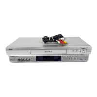
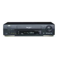
The following table lists the differing point(s) between models HR-S5901U, HR-S5911U, and HR-S5911U(C).
MODEL
HR-S5901U
ITEM
BODY COLOR BLACK PURE-SILVER
4. CHARTS AND DIAGRAMS
4.1 BOARD INTERCONNECTIONS ................................. 4-3
4.2 MAIN(VIDEO/N. AUDIO) SCHEMATIC DIAGRAM ..... 4-5
4.3 MAIN(S-SUB) SCHEMATIC DIAGRAM ...................... 4-7
4.4 MAIN(SYSCON) SCHEMATIC DIAGRAM .................. 4-9
4.5 MAIN(SW.REG) SCHEMATIC DIAGRAM................. 4-11
4.6 MAIN(TUNER) SCHEMATIC DIAGRAM................... 4-13
4.7 MAIN(FMA/DEMOD) SCHEMATIC DIAGRAM ......... 4-15
4.8 MAIN(FRONT) SCHEMATIC DIAGRAM................... 4-17
4.9 MAIN(TERMINAL) SCHEMATIC DIAGRAM ............. 4-19
4.10 2D DIGITAL SCHEMATIC DIAGRAM ..................... 4-21
4.11 2D DIGITAL CIRCUIT BOARD ................................ 4-23
4.12 MAIN CIRCUIT BOARD .......................................... 4-25
4.13 REMOTE CONTROLLER SCEMATIC DIAGRAM .. 4-27
4.14 WAVEFORMS ......................................................... 4-28
4.15 VOLTAGE CHARTS ................................................ 4-29
4.16
FDP GRID ASSIGNMENT AND ANODE CONNECTION
...4-29
4.17 CPU PIN FUNCTION .............................................. 4-30
4.18 SYSTEM CONTROL BLOCK DIAGRAM ................ 4-31
4.19 VIDEO BLOCK DIAGRAM ...................................... 4-33
4.20 AUDIO BLOCK DIAGRAM ...................................... 4-37
5. PARTS LIST
5.1 PACKING AND ACCESSORY ASSEMBLY<M1> ....... 5-1
5.2 FINAL ASSEMBLY<M2> ............................................. 5-2
5.3 MECHANISM ASSEMBLY<M4> ................................. 5-4
5.4 ELECTRICAL PARTS LIST ......................................... 5-6
MAIN BOARD ASSEMBLY<03> ..................................... 5-6
2D DIGITAL BOARD ASSEMBLY<05> ......................... 5-12
A/C HEAD BOARD ASSEMBLY<12> ........................... 5-13
REAR S JACK BOARD ASSEMBLY<29>..................... 5-13
FRONT S JACK BOARD ASSEMBLY<36> .................. 5-13
ADV.JOG/SW BOARD ASSEMBLY<38> ...................... 5-13
LOADING MOTOR BOARD ASSEMBLY<55>.............. 5-13
R.PAUSE BOARD ASSEMBLY<99>............................. 5-13
HR-S5911U HR-S5911U(C)
Note(s): Mark
is same as left.
 Loading...