(No.MB161)1-17
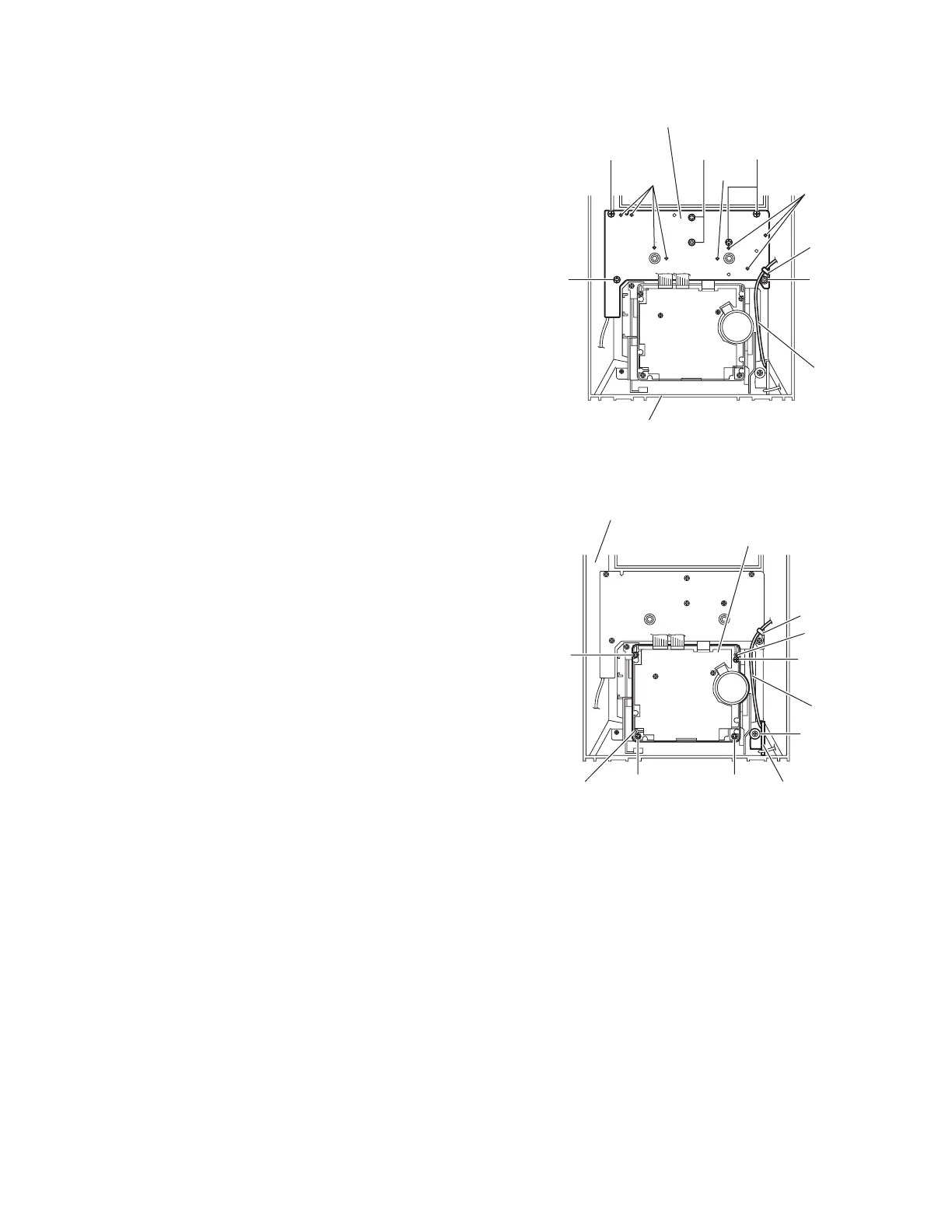
3.1.16 Removing the microphone board
(See Fig.30)
• Prior to performing the following procedure, remove the metal
cover and front panel assembly.
(1) From the inside of the front panel assembly, remove the six
screws AE and screw AE’ attaching the microphone board.
Reference:
• When attaching the microphone board, align the projections
ac of the front panel assembly in the holes of the microphone
board before attaching the screws AE and AE’.
• When attaching the screw AE', attach it with the wire holder.
Fig.30
3.1.17 Removing the headphone board
(See Fig.31)
• Prior to performing the following procedures, remove the metal
cover and front panel assembly.
(1) From the inside of the front panel assembly, remove the
screw AF attaching the headphone board.
(2) Remove the wire holder fixing the wire and take out the
headphone board.
Reference:
After attaching the headphone board, fix the wire with the wire
holder.
3.1.18 Removing the cassette mechanism assembly
(See Fig.31)
• Prior to performing the following procedure, remove the metal
cover and front panel assembly.
(1) From the inside of the front panel assembly, remove the
two screws AG and two screws AH attaching the cassette
mechanism assembly.
Reference:
When attaching the cassette mechanism assembly, align the
projections (ad,ae) in the holes of the cassette mechanism as-
sembly.
Fig.31
Front panel assembly
ac
AE AE AE
AE'AE
Wire
Wire holde
ac
ac
Microphone board
Front panel assembly
AG
AH
AH
AF
AG
Wire
ae
Wire holder
Cassette mechanism assembly
Headphone board
ad
 Loading...