1-12 (No.MB161)
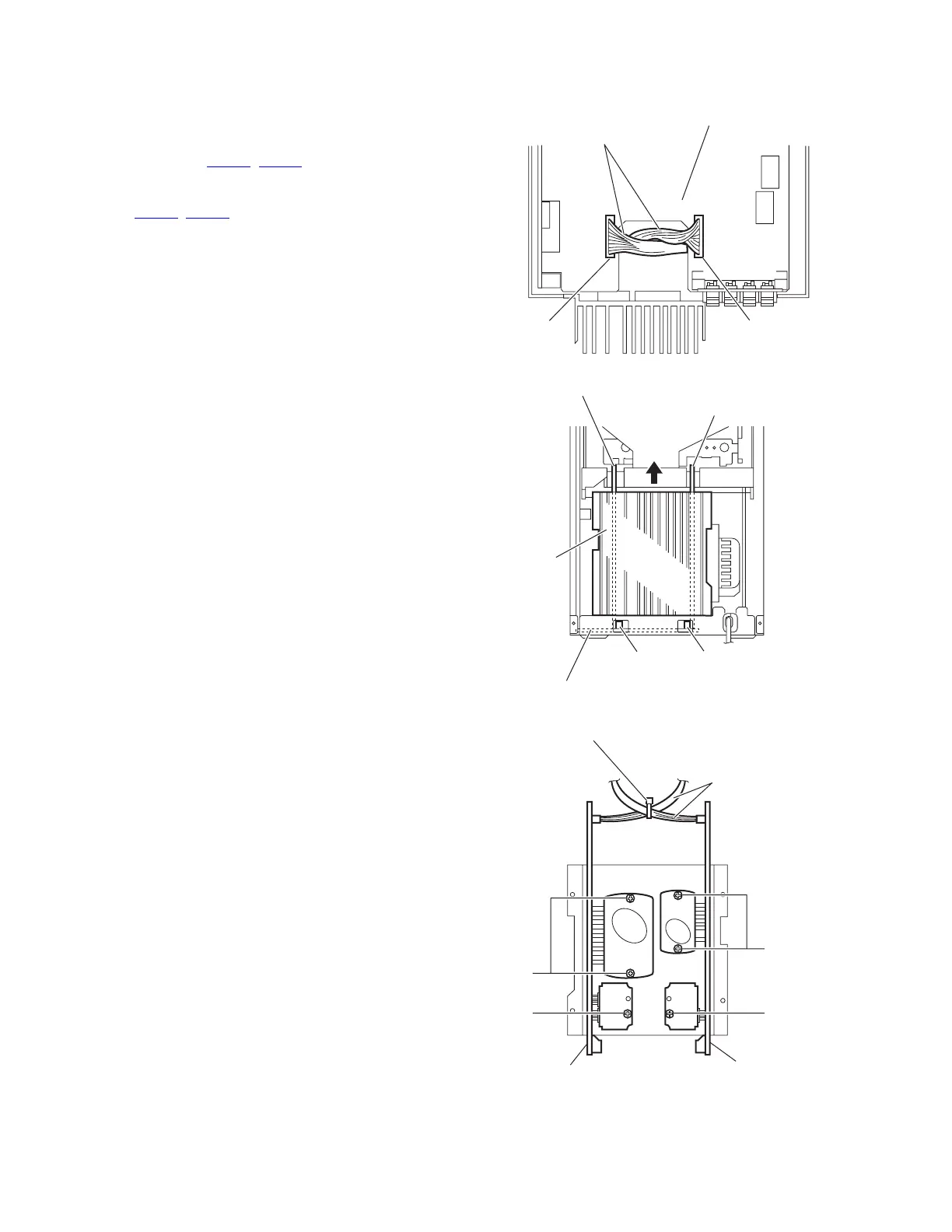
3.1.7 Removing the main amplifier board/subwoofer amplifier boards
(See Figs.15 to 17)
• Prior to performing the following procedures, remove the metal
cover, rear panel and main board.
(1) From the top side of the main body, disconnect the wires
from the connector (CN206
, CN208) on the bridge board.
(See Fig.15.)
(2) From the back side of the main body, disconnect the con-
nectors (CN600
, CN700) on the main amplifier/subwoofer
amplifier boards from the connection board in the direction
of the arrow. (See Fig.16.)
(3) From the side of the main amplifier/subwoofer amplifier
boards, remove the tie band bundling the wires. (See
Fig.17.)
Reference:
After reassembling, bundle the wires with the tie band.
(See Fig.17.)
(4) Remove the two screws M and screw N attaching the main
amplifier board. (See Fig.17.)
(5) Removing the two screws P and screw Q attaching the
subwoofer amplifier board. (See Fig.17.)
Fig.15
Fig.16
Fig.17
Wires
CN206CN208
Bridge board
CN606 CN700
Main amplifier board
Connection board
Heat sink
Subwoofer amplifier board
Main amplifier board
M
N
Q
P
Wires
Tie band
Subwoofer amplifier board
 Loading...