(No.MB161)1-11
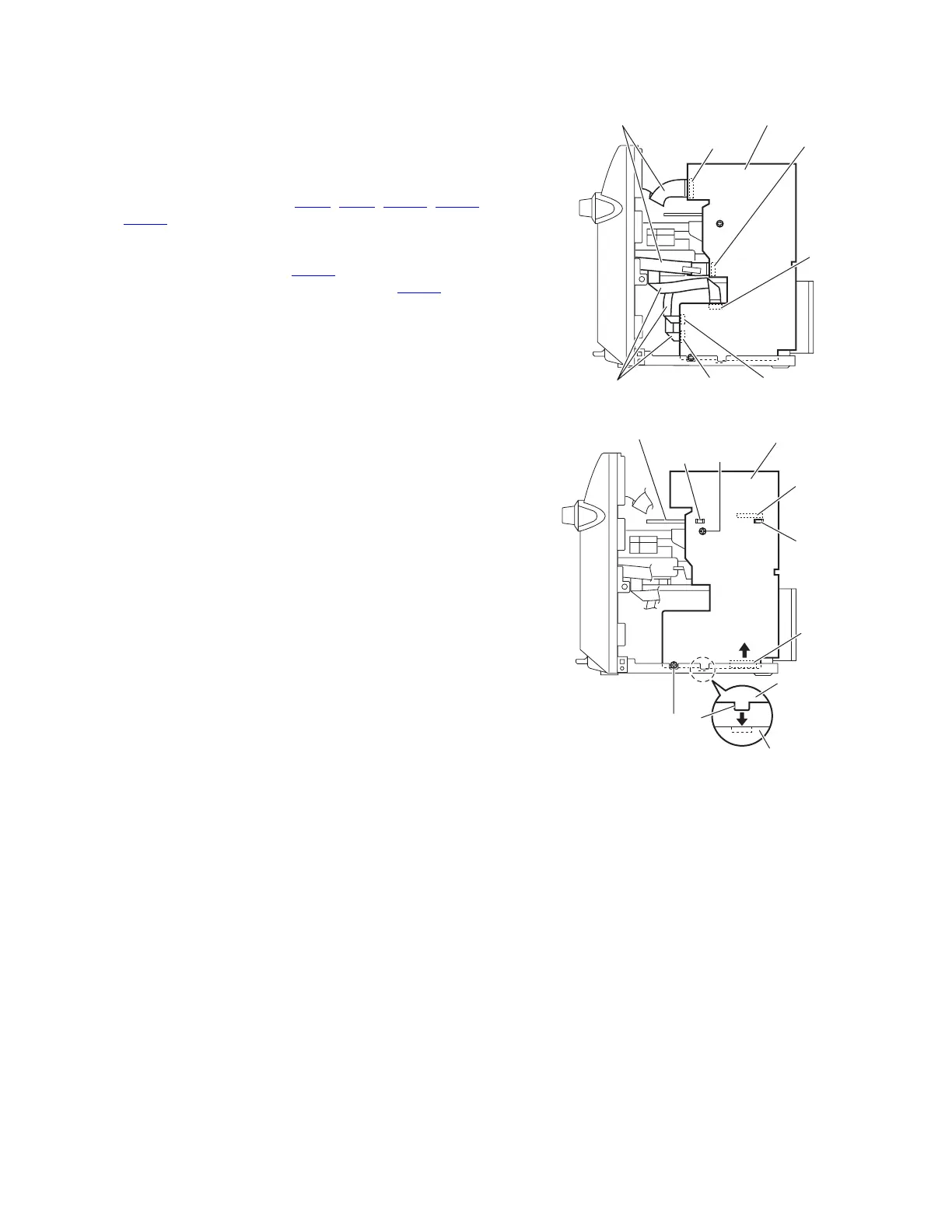
3.1.6 Removing the main board
(See Figs.13 and 14)
• Prior to performing the following procedures, remove the metal
cover and rear panel.
Reference:
Remove the tuner as required.
(1) From the right side of the main body, disconnect the card
wires from the connectors (CN43
, CN44, CN661, CN802,
CN803) on the main board. (See Fig.13.)
(2) Remove the two screws L attaching the main board. (See
Fig.14.)
(3) Disconnect the connector CN217
on the main board to-
ward this side and disconnect the connector CN501
on the
main board in the direction of the arrow. (See Fig.14.)
Reference:
• When attaching the main board, insert the sections f of the
bridge board in the hole of the main board. (See Fig.14.)
• Insert the section g of the main board in the hole of the chas-
sis base before attaching the screws L.
Fig.13
Fig.14
Card wires
Card wires
Main board
CN803
CN802
CN43
CN44
CN661
Chassis base
Main board
Main board
CN501
CN217
f
f
g
L
L
Bridge board
 Loading...