(No.MB161)1-23
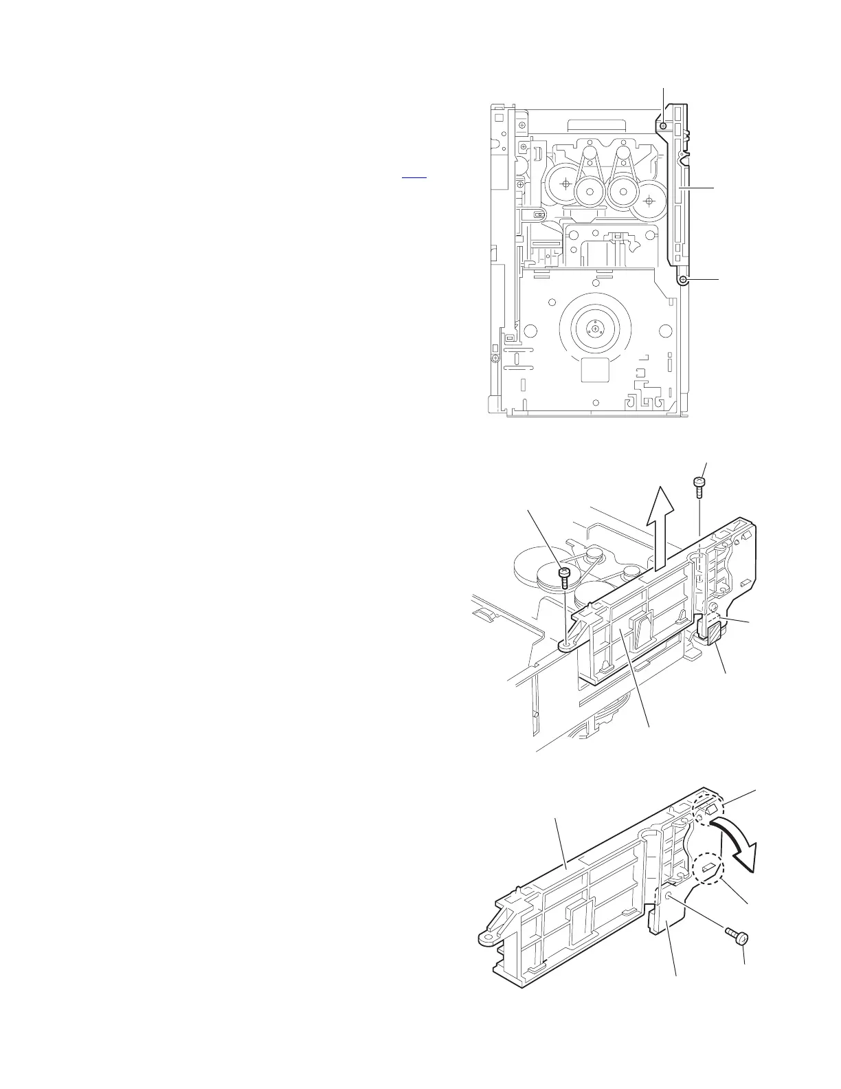
3.2.7 Removing the side (L)/ tray switch board
(See Fig.15 ~ 17)
• Prior to performing the following procedure, remove the tray
assembly.
(1) Remove the two screws H attaching the side (L) on top of
the body.
(2) From the side of the body, remove the spacer fixing the tray
switch board and motor board. Disconnect connector CN3
on the tray switch board and detach the side (L) upward.
(3) Remove the screw J attaching the tray switch board.
(4) Push the joint tab k of the side (L) in the direction of the ar-
row and remove the tray switch board outward, then re-
lease joint l.
Fig.15
Fig.16
Fig.17
H
H
Side (L)
CN3
Spacer
Side (L)
H
H
k
l
J
Side (L)
Tray switch board
 Loading...