1-13
HX-Z3
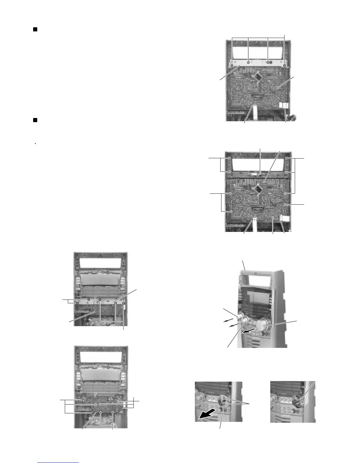
Remove the four screws S attaching the stay
bracket (1).
Disconnect the card wires from connector CN43 and
CN880 on the display system control board.
Remove the ten screws T attaching the display
system control board.
1.
2.
3.
Removing the display system control
board (See Fig.33,34)
Prior to performing the following procedure, remove
the display system control board.
Pull out preset knob, sound mode knob on the front
panel toward the front.
Pull out the volume knob encorder and remove the
two screws W attaching the knob holder.
Remove the nut from the front panel.
Remove the five screws U attaching the stay
bracket (2).
Remove the eight screws V attaching the bottom
board.
1.
2.
3.
4.
Removing the bottom board
(See Fig.33 ~ 37)
Fig.33
Fig.34
Fig.35
Fig.39 Fig.36 Fig.37
Fig.38
S
T
T
T
T
T
T
U
U
V
V
V
Display system
control board
Display system
control board
Stay bracket (1)
Stay bracket (2)
CN43 CN880
Front panel
Sound mode knob
Preset knob
Volume knob
CN43 CN880
Bottom board
Bottom board
Nut
Knob holder
W
 Loading...