1-20
HX-Z3
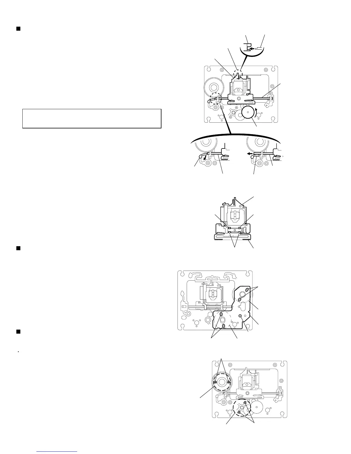
Turn the cam gear in the direction of the arrow to
move the pickup unit toward the center.
Extend the guide shaft stopper in the direction of the
arrow,move the guide shaft and pull out as shown in
the figure.
Pull out the pickup unit from the joint a.
Release the four joint b on the back on the pickup
unit to remove the CD rack.
1.
2.
3.
4.
Removing the Pickup unit
(See Fig.24 and 25)
On the back of the CD mechanism assembly,
unsolder the four soldering c attaching the CD
mechanism board, the spindle motor and the feed
motor.
Removing the screw A.
1.
2.
Removing the CD mechanism board
(See Fig.26 )
Prior to performing the following procedure,remove
the CD mechanism board.
Form the top side of the CD mechanism assembly,
remove the two screws B and two screws C
attaching the spindle motor and the feed motor
respsctively.
1.
Removing the Spindle motor/Feed motor
(See Fig.27)
When reassenbling, attch the pickup unit
to the chassis base firmly at the joint a.
CAUTION:
A
Pickup unit
Pickup unit
Chassis base
Guide shaft
Cam gear
Guide shaft stopper
Guide shaft stopper
Guide shaft
Guide shaft
Joint a
B
C
Pickup unit
Joint b
Joint b CD rack
Soldering c
Spindle motor
Spindle motor
Feed motor
Feed motor
CD mechanism board
Soldering c
Joint b
Fig.25
Fig.26
Fig.27
Fig.24
 Loading...