(No.MA254)1-13
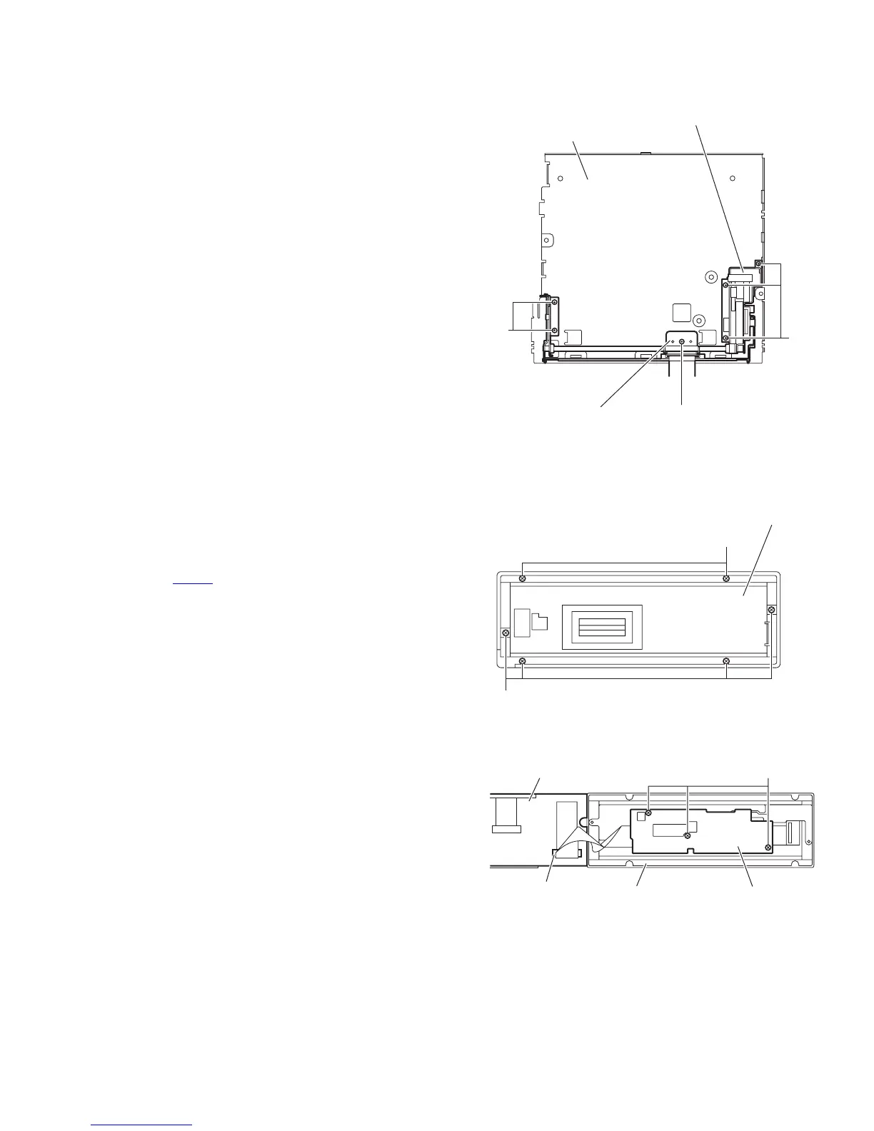
3.1.9 Removing the front door mechanism assembly
(See Fig.14)
• Remove the front panel assembly, side heat sink, top chassis
assembly main board and rear bracket.
(1) From the top side of the bottom chassis assembly, remove
the screw Q attaching the FPC guide to the bottom chassis.
(2) Remove the five screws R attaching the front door mecha-
nism assembly to the bottom chassis.
Reference:
When attaching the screws Q and R, apply a locking
agent them.
(3) Take out the front door mechanism assembly from the bot-
tom chassis.
Fig.14
3.1.10 Removing the panel A control board and panel panel B control board
(See Figs.15 and 16)
• Remove the panel assembly.
(1) From the back side of the panel assembly, remove the six
screws S attaching the rear cover to the panel assembly.
(See Fig.15.)
(2) From the inside of the rear cover, release the lock of the
connector CN583
on the panel A control board and discon-
nect the card wire. (See Fig.16.)
(3) Remove the three screws T attaching the panel B control
board and take out the panel B control board from the rear
cover. (See Fig.16.)
Note:
Do not lose the compression spring when taking out the panel
A control board. (See Fig.16.)
Fig.15
Fig.16
Bottom chassis
R
R
Q
FPC guide
Front door mechanism assembly
S
S
Rear cove
Panel A control board
Panel B control board
CN583
Rear cover
T