1-12 (No.MA254)
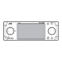
3.1.7 Removing the rear bracket
(See Fig.11 to 13)
• Remove the panel assembly, side heat sink and top chassis
assembly.
(1) Remove the screw J, screw J', two screws K and screw M
attaching the rear bracket. (See Fig. 11.)
Reference:
When attaching the screw J', attach the wire holder with
it as before.
(2) Remove the screw N attaching the wire holder. (See
Fig.11.)
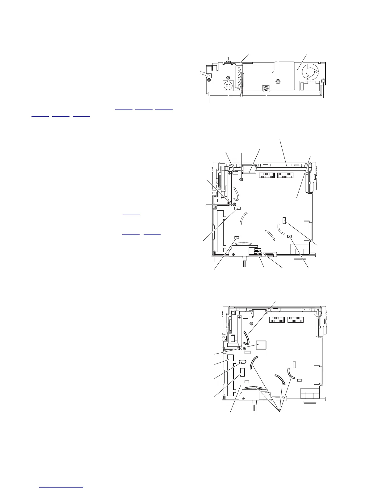
(3) Release the lock of the connector (CN301
, CN311, CN361,
CN861
, CN871, CN931) on the main board in an upward
direction. (See Fig.12.)
(4) Remove the car cable from the rear bracket. (See Fig.12.)
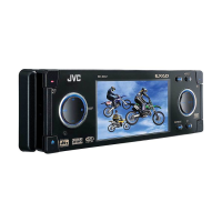
Note:
When attaching the car cable, do not touch the cable to
X31, IC31, TU1 and IC701 then pushing down all the ca-
ble to main board side by wire clamp. (See Fig.13.)
(5) Take out the rear bracket from the bottom chassis assem-
bly.
3.1.8 Removing the main board
(See Figs.12)
• Remove the panel assembly, side heat sink, top chassis as-
sembly and rear bracket.
(1) Release the lock of the connector CN962
on the main
board in an upward direction and disconnect the flexible
wire.
(2) Release the lock of the connector (CN881
, CN891) and
disconnect the card wire.
(3) Remove the two screws P attaching the main board to the
bottom chassis assembly.
(4) Take out the main board from the bottom chassis assem-
bly.
Fig.11
Fig.12
Fig.13
M
KJ'
J
Rear bracketWire holder
N
Bottom chassis assembly
CN962
CN891
CN881
CN931
CN871
CN361
CN311
CN861
CN301
Main board
P
P
TU1
X31
IC31
Wire clamp
Main board
Wire clamp
IC701