1-8 (No.MA154)
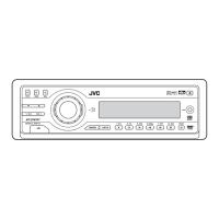
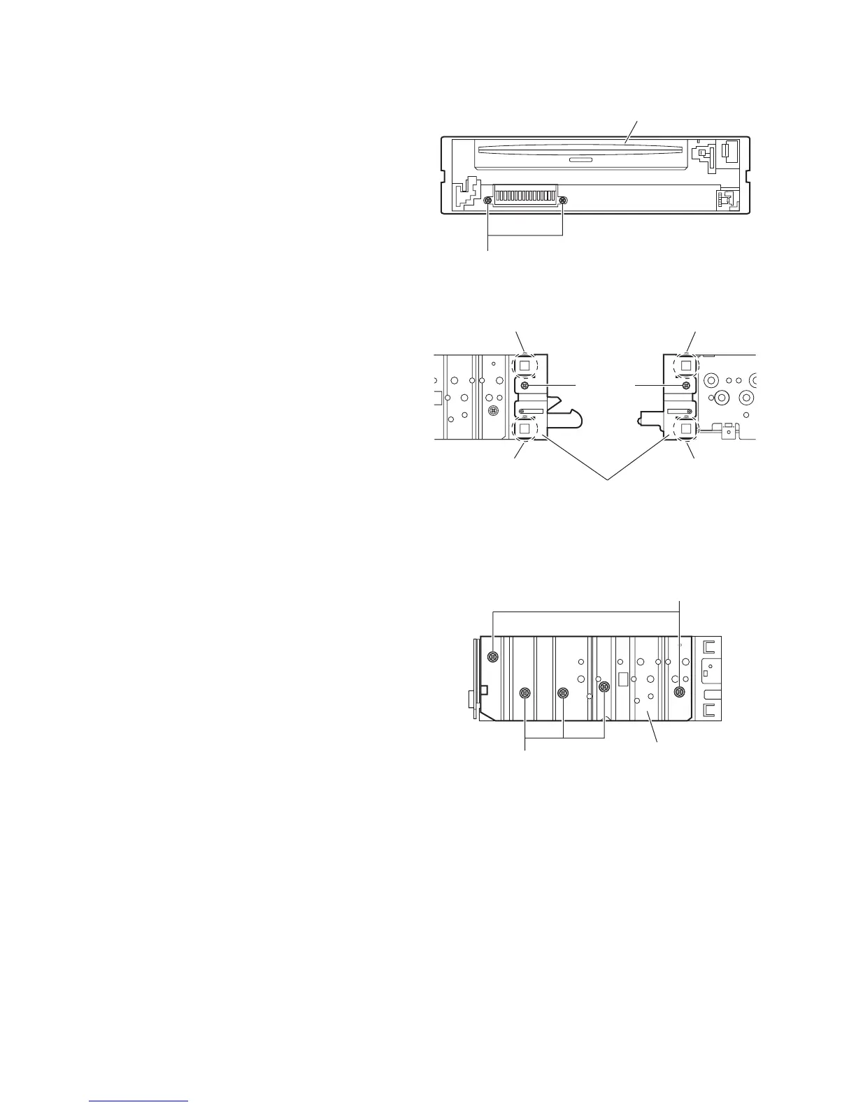
3.1.3 Removing the front chassis assembly
(See Figs.3 and 4)
• Remove the front panel assembly and bottom cover.
(1) From the front side of the main body, remove the two
screws A attaching the front chassis assembly. (See
Fig.3.)
(2) From the both sides of the main body, remove the two
screws B attaching the front chassis assembly. (See
Fig.4.)
(3) Release the two joints d and two joints e. (See Fig.4.)
Fig.3
Fig.4
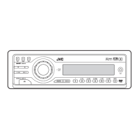
3.1.4 Removing the side heat sink
(See Fig.5)
Reference:
Remove the front panel and front chassis assemblies as re-
quired.
From the left side of the main body, remove the two screws C and
three screws D attaching the side heat sink.
Fig.5
A
Front chassis assembly
d
d
Front chassis assembly
B
e
e
B
C
D
Side heat sink
 Loading...