EasyManuals Logo

JVC KD-G501 Service Manual

JVC KD-G501
57 pages
To Next Page IconTo Next Page
To Previous Page IconTo Previous Page
Page #23 background imageLoading...
Page #23 background image
(No.MA038)1-23
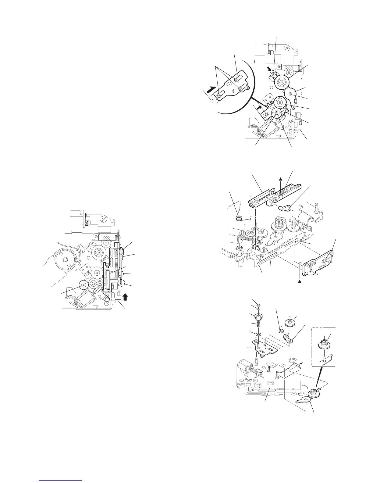
3.2.17 Removing the gears
(See Figs.37 to 40)
Prior to performing the following procedure, remove the top
cover, chassis unit, top plate assembly and pickup unit.
Pull out the loading gear 3. (See Fig.35.)
(1) Pull out the feed gear.
(2) Move the loading plate assembly in the direction of the ar-
row to release the L side plate from the two slots m' of the
chassis rivet assembly. (See Fig.37.)
(3) Detach the loading plate assembly upward from the chas-
sis rivet assembly while releasing the joint n'. Remove the
slide hook and loading plate spring from the loading plate
assembly.
(4) Pull out the loading gear 2 and remove the change lock le-
ver.
(5) Remove the E ring and washer attaching the changer gear
2.
(6) The changer gear 2, change gear spring and adjusting
washer come off.
(7) Remove the loading gear 1.
(8) Move the change plate rivet assembly in the direction of the
arrow to release from the three shafts of the chassis rivet
assembly upward. (See Fig.38.)
(9) Detach the loading gear plate rivet assembly from the shaft
of the chassis rivet assembly upward while releasing the
joint p'. (See Figs.38 and 40.)
(10) Pull out the loading gear 4.
Fig.37
Fig.38
Fig.39
Fig.40
Slot m'
Slot m'
Joint n'
Feed gear
Loading plate assembly
L side plate
Chassis rivet assembly
Joint p'
Loading gear 4
Loading gear 2
Loading gear 1
Change gear 2
Loading gear plate
rivet assembly
E ring
Shafts
Change plate
rivet assembly
Shaft
Chassis rivet assembly
Loading plate assembly
Loading plate spring
Chassis rivet assembly
Slot m'
Slot m'
Joint n'
L side plate
Slide hook
Loading gear 2
Loading gear 4
Change gear 2
Loading gear 1
E ring
Washer
Change gear spring
Loading gear plate rivet assembly
Chassis rivet assembly
Adjusting washer
Change plate
rivet assembly
Change lock lever

Other manuals for JVC KD-G501

Questions and Answers:

Question and Answer IconNeed help?

Do you have a question about the JVC KD-G501 and is the answer not in the manual?

JVC KD-G501 Specifications

Audio Amplifier Specifications IconAudio Amplifier Specifications
maximum power output front50 W per channel
maximum power output rear50 W per channel
continuous power output front19 W per channel into 4 Ω, 40 Hz to 20 000 Hz at no more than 0.8% total harmonic distortion
continuous power output rear19 W per channel into 4 Ω, 40 Hz to 20 000 Hz at no more than 0.8% total harmonic distortion
load impedance4 Ω (4 Ω to 8 Ω allowance)
tone control range bass±10 dB at 100 Hz
tone control range treble±10 dB at 10 kHz
frequency response40 Hz to 20 000 Hz
signal-to-noise ratio70 dB
line-out level/impedance2.0 V/20 kΩ load (full scale)
output impedance1 kΩ
CD Player Specifications IconCD Player Specifications
operating voltageDC 14.4 V (11 V to 16 V allowance)
allowable operating temperature0°C to +40°C
dimensions installation size182 mm × 52 mm × 150 mm
dimensions panel size188 mm × 58 mm × 12 mm
mass1.4 kg (excluding accessories)
frequency response5 Hz to 20 000 Hz
dynamic range96 dB
signal-to-noise ratio98 dB
max. bit rate320 Kbps
Tuner Specifications IconTuner Specifications
frequency range FM87.5 MHz to 108.0 MHz
frequency range AM (MW)522 kHz to 1 620 kHz
frequency range AM (LW)144 kHz to 279 kHz
usable sensitivity FM11.3 dBf (1.0 µV/75 Ω)
50 dB quieting sensitivity FM16.3 dBf (1.8 µV/75 Ω)
alternate channel selectivity (400 kHz) FM65 dB
frequency response FM40 Hz to 15 000 Hz
stereo separation FM30 dB
capture ratio FM1.5 dB
sensitivity MW20 µV
selectivity MW35 dB
sensitivity LW50 µV

Related product manuals