1-8 (No.MA038)
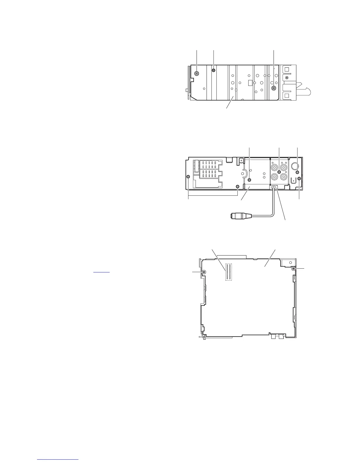
3.1.4 Removing the side panel
(See Fig.5)
• Prior to performing the following procedure, remove the front
panel assemblyÅ@as required.
(1) Remove the screw C and two screws D attaching the side
panel on the left side of the main body, and remove the side
panel.
Fig.5
3.1.5 Removing the rear bracket
(See Fig.6)
• Prior to performing the following procedure, remove the bottom
cover.
(1) Remove the three screws E, screw F and three screws G
attaching the rear bracket on the back side of the main
body.
(2) Remove the rear bracket.
Reference:
During reassembly, before fixing the rear bracket onto the
main body, inserts the steering cable.(KD-G501 E)
3.1.6 Removing the main board
(See Figs.6 and 7)
• Prior to performing the following procedure, remove the front
panel assembly, bottom cover, front chassis assembly and
side panel.
• Remove the rear bracket as required.
(1) Remove the three screws E attaching the rear bracket on
the back side of the main board. (See fig.6.)
(2) Remove the two screws H attaching the main board. (See
fig.7.)
(3) Disconnect the connector CN501
and remove the main
board. (See fig.7.)
Reference:
Remove the rear bracket from the main body as required. (See
“3.1.5 Removing the rear bracket”.)
Fig.6
Fig.7
Side panel
CCD
GG
E
Rear bracket
Insert the steering cable
into the slot.
F
E
Main board
H
H
CN501
 Loading...