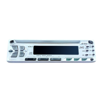
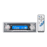
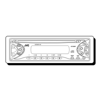
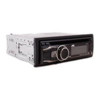
KD-S621
1-7
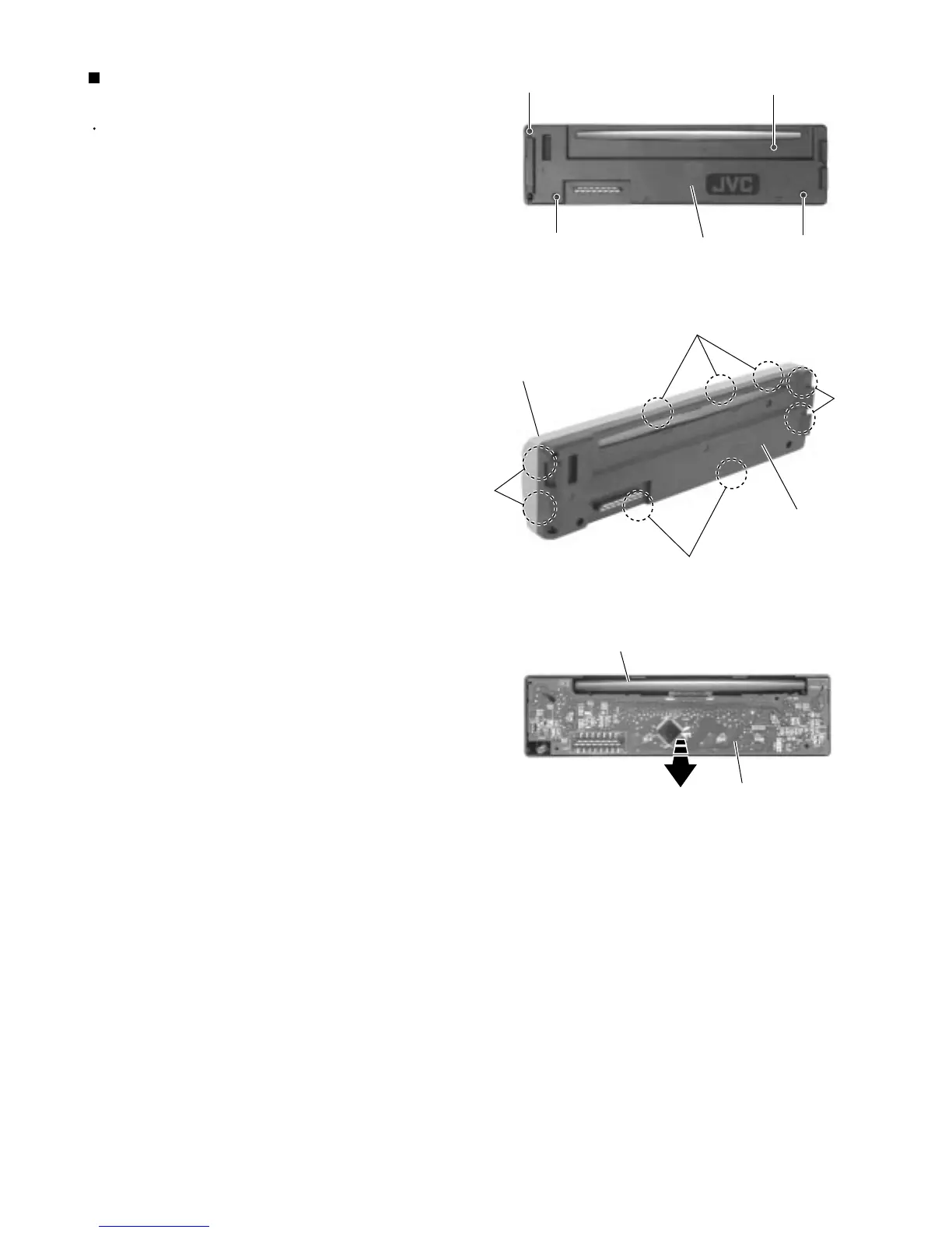
Prior to performing the following procedure, remove
the front panel assembly.
Remove the four screws G attaching the rear cover
on the back of the front panel assembly.
Unjoint the nine joints c with the front panel and the
rear cover.
Remove the control switch board on the back of the
front panel.
1.
2.
3.
Removing the control switch board
(See Fig.10 to 12)
Fig.10
Fig.11
Fig.12
G
G
G
G
Rear cover
Joints c
Joints c
Front panel
Rear cover
Front panel
Control switch board
Joints c
Joints c