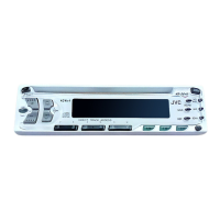
KD-S641
(No.49769)1-5
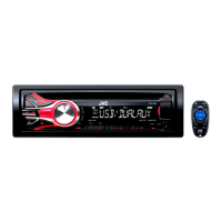
2.1.3 Removing the heat sink
(See Fig.4)
(1) Remove the two screws B and two screws C on the left
side of the main body.
Fig.4
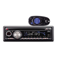
2.1.4 Removing the bottom cover
(See Figs.5 and 6)
• Prior to performing the following procedure, remove the front
panel assembly, front chassis assembly and heat sink.
(1) Turn over the body and release the two joints c, two joints
d and joint e.
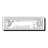
CAUTION:
Do not damage the main board when releasing the joint e us-
ing a screwdriver. (See Figs.5 and 6.)
Fig.5
Fig.6
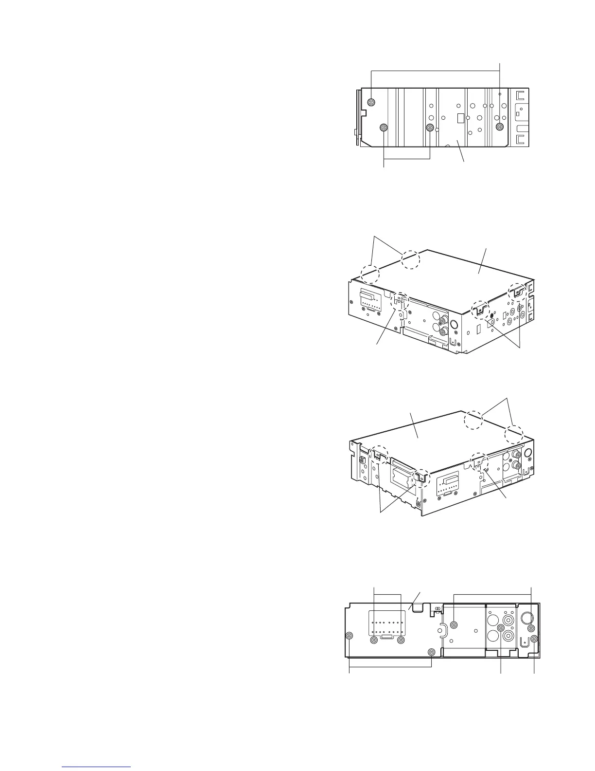
2.1.5 Removing the rear bracket
(See Fig.7)
• Prior to performing the following procedure, remove the front
panel assembly, front chassis assembly, heat sink and bottom
cover.
(1) Remove the three screws D, three screws E and two
screws F on the back of the body.
(2) Remove the rear bracket.
Fig.7
B
C
Heat sink
Joint c
Joint d
Joint e
Bottom cover
Joint d
Joint c
Joint e
Bottom cover
EF
DD
E
Rear bracket
 Loading...